Heat pump device
A heat pump device and heat transfer technology, applied in household refrigeration devices, refrigeration device isolation, pumps, etc., can solve problems such as productivity deterioration, slow curing speed, mold corrosion, etc., and achieve the effect of inhibiting decomposition reactions
- Summary
- Abstract
- Description
- Claims
- Application Information
AI Technical Summary
Problems solved by technology
Method used
Image

Examples
Embodiment approach 1
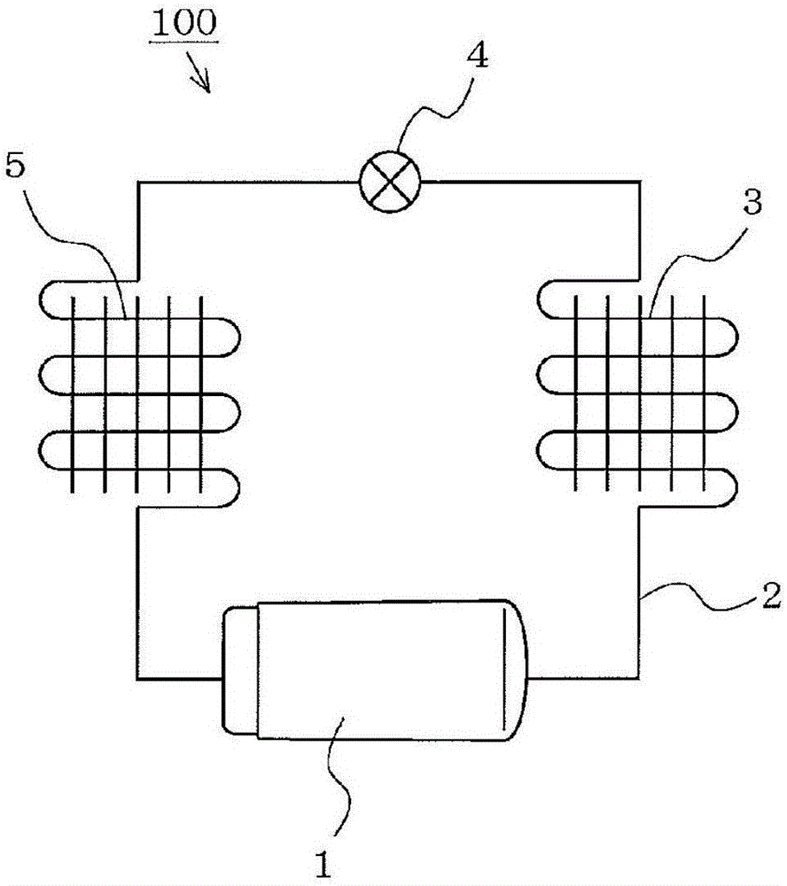
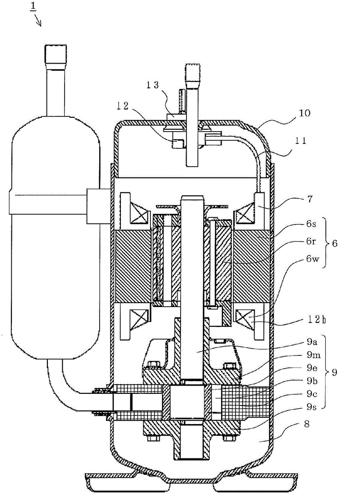
[0058] figure 1 and figure 2 The heat pump device according to Embodiment 1 of the present invention will be described. figure 1 To show the basic structure of the refrigerant circuit diagram, figure 2 It is a sectional view showing a side view of a part (compressor). It should be noted that each figure is schematically depicted, and the present invention is not limited to the depicted manner.
[0059] (Refrigerant cycle)
[0060] in figure 1 In the heat pump device 100, a compressor 1 for compressing the refrigerant, a condenser 3 for condensing the refrigerant flowing from the compressor, a throttling mechanism 4 for adiabatic expansion of the refrigerant flowing from the condenser 3, The evaporator 5 that evaporates the refrigerant flowing out of the flow mechanism 4, and the refrigerant pipe 2 that connects these in order to circulate the refrigerant. It should be noted that the refrigerant pipe 2 may be provided with a switching valve (for example, a four-way valve) for ch...
Embodiment approach 2
[0107] Figure 4 The heat pump device according to the second embodiment of the present invention is described. It shows trans-1,1,2-trifluoroethylene (R1123(E)), mixing ratio, and mixture ratio of ethylene-based hydrogen fluoride refrigerant mixed with R32 at 250°C. The pressure-weight ratio correlation diagram of the range where the disproportionation reaction occurs when the pressure is changed. In the heat pump device according to the second embodiment of the present invention, the refrigerant circuit, the compressor, the electric motor, and the refrigerating machine oil have the same configuration as in the first embodiment, except that the configuration of the refrigerant is changed.
[0108] by Figure 4 It is understood that as the mixing ratio of R1123(E) increases, and as the pressure increases, the disproportionation reaction tends to occur easily.
[0109] In the heat pump device of Embodiment 2, the refrigerant pressure is 6 MPa even at the maximum. In the pressure ...
Embodiment approach 3
[0112] The refrigerant used in the third embodiment is a monomer composed of either propylene-based fluorinated hydrocarbon (HFO-1234yf) or ethylene-based hydrogen fluoride; or a composite composed of two or more types; or, containing difluoromethane ( A composite of a mixture of HFC-32) and ethylene-based hydrogen fluoride has a ratio of ethylene-based hydrogen fluoride to R32 of 70% by weight or less.
[0113] The ethylene-based hydrogen fluoride is trans-1,2-difluoroethylene (R1132(E)), fluoroethylene (R1141), cis-1,2-difluoroethylene (R1132(Z)), 1,1-difluoroethylene (R1132(Z)) Either of fluoroethylene (R1132a) and 1,1,2-trifluoroethylene (R1123), one or more of them may be mixed.
[0114] Propylene-based fluorinated hydrocarbons and ethylene-based hydrogen fluoride refrigerants are thermally and chemically unstable, and are prone to decomposition and polymerization caused by chemical reactions. Especially in the high temperature part, the chemical reaction of the refrigerant i...
PUM
 Abstract
Description
Claims
Application Information
 - R&D
- Intellectual Property
- Life Sciences
- Materials
- Tech Scout
- Unparalleled Data Quality
- Higher Quality Content
- 60% Fewer Hallucinations
Browse by: Latest US Patents, China's latest patents, Technical Efficacy Thesaurus, Application Domain, Technology Topic, Popular Technical Reports.
© 2025 PatSnap. All rights reserved.Legal|Privacy policy|Modern Slavery Act Transparency Statement|Sitemap|About US| Contact US: help@patsnap.com