Device and method for measuring soil water flow velocity on basis of thermal pulse method

A soil water and heat pulse technology, applied in the direction of using thermal variables to measure fluid velocity, etc., can solve the problems affecting measurement accuracy, distance influence, inability to use, etc., and achieve the effects of accurate measurement, stable heat transfer, and simple analysis method.

Active Publication Date: 2016-12-07
CHINA AGRI UNIV
View PDF11 Cites 8 Cited by
  • Summary
  • Abstract
  • Description
  • Claims
  • Application Information

AI Technical Summary

Problems solved by technology

[0003] In the measurement of water flow velocity in porous media or thin surface layers, such as gravel surface layers or roads, more accurate flow velocity data can generally be obtained by using pigment or electrolyte pulse measurement methods. The electrolyte pulse method is a very short time upstream of the flowing water flow. Electrolyte is injected into the water flow (the process can be regarded as a pulse waveform with a very small duty cycle). When the probe arranged downstream of the water flow detects electrolyte, the instrument records the time from the start of electrolyte injection to the detection of electrolyte. The time and the distance from the probe to the electrolyte pulse generating device correspond to a flow velocity relationship, which can realize the measurement of the water flow velocity on the surface layer. Although the electrolyte pulse method is simple and accurate, in soil or the dead leaf layer in similar forests, due to its porous medium composition complex, where electrolytes are absorbed in large quantities, and accurate water flow data cannot be provided using this tracer method
[0004] The thermal pulse method measurement corresponds to the electrolyte pulse method. This method uses heat to replace the electrolyte as a tracer, and calculates the velocity by detecting the temperature change of the water flow in the direction of the porous medium flow. The current thermal pulse probe adopts a structure in a Three very thin probes are arranged horizontally on the probe. The middle probe is a heating resistance wire, and the probes on both sides are thermocouple sensors. The three probes are inserted into the soil and parallel to the direction of water flow. The middle probe gives a heat pulse. Under the action of soil conduction and water flow, the heat given by it changes the temperature of the soil interval around the probe. The temperature-time change data collected by the thermocouples on both sides of the probe distribution is used to fit the theoretically derived heat exchange. The model relational formula, the model is based on the thermal conduction relational formula of the porous medium flow field (that is, in a Cartesian coordinate system, there is a heat conduction differential equation for convection in the three-dimensional unsteady state), given a finite heating time and an infinite heating heat source as Boundary conditions, to obtain the analytical solution of the flow field heat transfer relation, the solution uses the temperature difference between the upstream and downstream points of the flow field (that is, the position of the probe thermocouple) as a variable, so as to obtain the flow field velocity, but this The problem with this probe is that its diameter is too small, and the distance between the thermocouple sensor and the heating resistance wire will be affected when it is inserted into the soil, thereby affecting its measurement accuracy; at the same time, the theoretical derivation heat transfer model of the probe is considered The finite effect of the probe (finite thermal conductivity and finite diameter) has a certain influence on the calculated results after its measurement

Method used


Image

  • Device and method for measuring soil water flow velocity on basis of thermal pulse method
  • Device and method for measuring soil water flow velocity on basis of thermal pulse method
  • Device and method for measuring soil water flow velocity on basis of thermal pulse method

Examples


Embodiment Construction

[0025] The present invention will be described in detail below in conjunction with the accompanying drawings. However, it should be understood that the accompanying drawings are provided only for better understanding of the present invention, and they should not be construed as limiting the present invention.

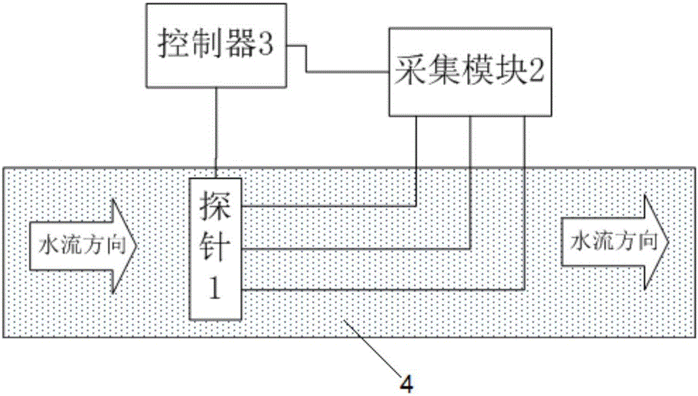
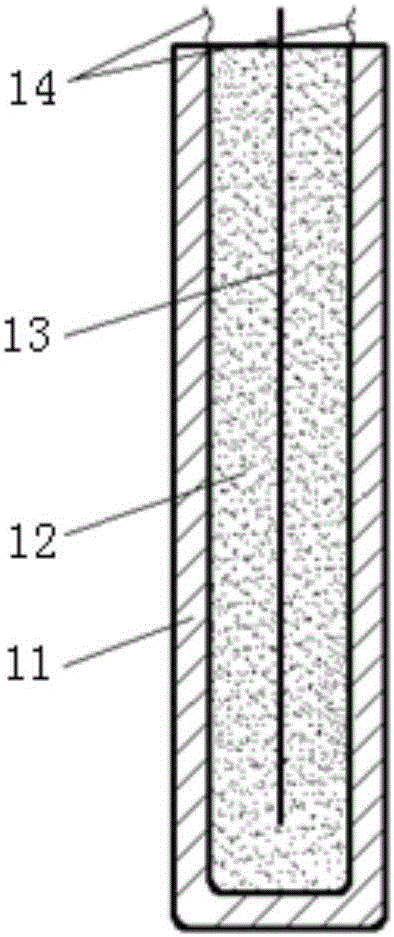
[0026] like Figure 1~2 As shown, the device for measuring soil water flow rate based on thermal pulse method of the present invention includes a probe 1, an acquisition module 2 and a controller 3; the probe 1 is all vertically inserted into the soil 4, and is in close contact with the soil 4, and the probe 1 includes Heat-conducting metal steel shell 11, insulating and heat-conducting material 12, heating resistance wire 13 and thermocouple bare wire 14, heat-conducting metal steel shell 11 is filled with high-temperature-resistant insulating and heat-conducting material 12 such as magnesium oxide, and insulating and heat-conducting material 12 is used for conduction ...


PUM


Abstract

The invention relates to a device and method for measuring the soil water flow velocity on the basis of a thermal pulse method. The device comprises a probe, a collection module and a controller; the probe is perpendicularly inserted into soil completely, closely makes contact with the soil and comprises a thermal conducting metal steel shell, a heating resistance wire and thermocouple bare wires, a through hole is formed in the center of the top of the thermal conducting metal steel shell, the heating resistance wire penetrates through the through hole to be fixedly inserted into the probe, the thermocouple bare wires for measuring surface temperature signals of the thermal conducting metal steel shell are uniformly distributed at the periphery of the heating resistance wire, the output ends of the thermocouple bare wires are connected with an input port of the collection module through signal transmission lines separately, and the controller is connected with the heating resistance wire and the collection module separately and used for controlling the heating time of the heating resistance wire to enable heat to be capable of being transmitted into the soil in the mode of an instantaneous pulse and controlling the collection module to conduct data collection. The device and method are precise in measurement and stable in thermal transmission and can be widely applied to soil water flow velocity measurement.

Description

technical field [0001] The invention relates to a device and method for measuring soil water flow velocity, in particular to a device and method for measuring soil water flow velocity based on a thermal pulse method. Background technique [0002] Soil water refers to the moisture in the soil layer from below the ground surface to above the groundwater table (water table). The rational use of water resources provides effective theoretical guidance. For the study of soil water, it is necessary to accurately grasp its migration parameters. Due to the influence of terrain, soil, vegetation, climate and other conditions, the characteristics of soil water migration are complex, so it can be accurately studied during research. It is particularly important to measure the soil water flow rate. [0003] In the measurement of water flow velocity in porous media or thin surface layers, such as gravel surface layers or roads, more accurate flow velocity data can generally be obtained by...

Claims


Application Information

Patent Timeline
Patent Type & Authority Applications(China)
IPC IPC(8): G01P5/10
CPCG01P5/10
Inventor 李淑艳刘成王伟
Owner CHINA AGRI UNIV
Why Eureka
Try Eureka