Method for cutting ultra-thin silicon wafer by superfine steel wire

A wire cutting and silicon wafer technology, which is used in fine working devices, manufacturing tools, stone processing equipment, etc., can solve the problems of affecting the cooling performance of cutting fluid, increasing the risk of wire breakage, and low yield rate.

Active Publication Date: 2016-12-14
SHANGHAI SHENHE THERMO MAGNETICS ELECTRONICS CO LTD
View PDF11 Cites 17 Cited by
  • Summary
  • Abstract
  • Description
  • Claims
  • Application Information

AI Technical Summary

Problems solved by technology

[0003] In order to reduce the cost, reducing the thickness of the silicon wafer is an effective method, but cutting the steel wire too thin will cause problems: in the production process of the steel wire, the smaller the diameter of the busbar, the more difficult it is to draw the wire, the higher the broken wire rate, and the lower the yield rate; The smaller the diameter of the steel wire during the cutting process, the smaller the tension required during cutting, and the higher the requirements for the tension control system of the cutting equipment; the thinner the wire diameter of the busbar, the cutting ability of the steel wire will be affected during the cutting process, and the risk of wire breakage will be lower. It will increase; the thinner the steel wire, the smaller the spindle groove distance, the smaller the distance between the steel wires, and under the action of cooling water, the steel wires will be easier to merge together, and the temperature increase can properly reduce the surface tension of the liquid, but the temperature The increase will affect the cooling performance of cutting fluid, etc.

Method used


Image

  • Method for cutting ultra-thin silicon wafer by superfine steel wire

Examples


Embodiment 1

[0017] A method for cutting ultra-thin silicon wafers with ultra-thin steel wires, comprising the following steps: (1) slotting a main shaft, (2) sticking sticks, (3) configuring cooling liquid, (4) cutting, (5) blanking, ( 6) degumming and cleaning, (7) detection; the step (3) configures cooling fluid, the cooling fluid is pure water and water-based cutting fluid, and the concentration of the cutting fluid is 2.0%; the step (4) is used for cutting and cutting steel wire 60um diamond wire, diamond particles with a diameter of 6um, a spindle groove distance of 0.19mm, a cutting blade thickness of 115um, a groove angle of 24°, a groove depth of 0.28mm, and a main cutting speed of 1.3mm / min for bidirectional cutting. The groove bottom width is 55um. The line speed is 1600m / min.

[0018] When the tension is set to 5N, 6N, 7N, 8N, 9N, and 10N, the greater the tension, the higher the wire breakage rate, and the lower the tension, the lower the cutting efficiency. The best effect is...

Embodiment 2

[0023] A method for cutting ultra-thin silicon wafers with ultra-thin steel wires, comprising the following steps: (1) slotting a main shaft, (2) sticking sticks, (3) configuring cooling liquid, (4) cutting, (5) blanking, ( 6) degumming and cleaning, (7) detection; the step (3) configuration coolant, the coolant is pure water and water-based cutting fluid; the step (4) cutting, cutting steel wire uses 60um diamond wire, diamond particles use The diameter is 6um particles, the tension is 8N, the spindle groove distance is 0.19mm, the cutting blade thickness is 115um, the groove angle is 24°, the groove depth is 0.28mm, and the cutting speed of the main body is 1.3mm / min for bidirectional cutting. The groove bottom width is 55um. The line speed is 1600m / min.

[0024] The concentration of cutting fluid is 0.3%, 0.6%, 1%, 1.3%, 1.6%, and 2.0%, respectively. The concentration of 0.6% to 2.0% is better. Increase the cost and increase the viscosity of the cutting fluid, which is no...

Embodiment 3

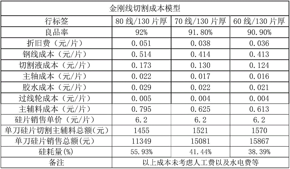
[0029] A method for cutting ultra-thin silicon wafers with ultra-thin steel wires, comprising the following steps: (1) slotting a main shaft, (2) sticking sticks, (3) configuring cooling liquid, (4) cutting, (5) blanking, ( 6) degumming and cleaning, (7) detection; the step (3) configures cooling fluid, the cooling fluid is pure water and water-based cutting fluid; the step (4) cutting, 60um steel wire, diamond particles with a diameter of 6um Particles, the tension is 8N, the cutting fluid concentration is 2%, the spindle groove distance is 0.21mm, the cutting sheet thickness is 130um, the groove angle is 24°, the groove depth is 0.28mm, and the cutting speed of the main body is 1.3mm / min for bidirectional cutting. The groove bottom width is 55um. The line speed is 1600m / min.

[0030] Comparing the use of 60um diamond wire with 70um and 80um diamond wire cutting, the 60um diamond wire has the lowest cutting cost, the highest income, the lowest silicon consumption, and the be...


PUM

PropertyMeasurementUnit
diameteraaaaaaaaaa
particle diameteraaaaaaaaaa

Abstract

The invention relates to a method for cutting ultra-thin silicon wafer by a superfine steel wire. The method comprises the following steps of: (1) forming slots in a man shaft; (2) sticking bars; (3) preparing a cooling liquid; (4) cutting; (5) unloading; (6) degumming and cleaning; and (7) detecting; the cooling liquid prepared in the step (3) is pure water and a water-based cutting fluid with concentration being 0.6%-2.0%; and during cutting in the step (4), cutting steel wires are 60 [mu]m diamond wires, diamond particles are particles with diameter being 6-8 [mu]m, tension is set to be 7-9 N, and slot pitch of the main shaft is 0.19-0.210 mm. According to the method, single crystal slicing yield is further reduced, slicing thickness is reduced, silicon loss is reduced and processing cost is reduced; and meanwhile, a wire braking rate can be reduced, yield is increased, and wire doubling is avoided.

Description

technical field [0001] The invention relates to a silicon chip cutting process, in particular to a method for cutting an ultra-thin silicon chip with an ultra-thin steel wire which further reduces slice thickness, reduces silicon consumption, and reduces processing costs. Background technique [0002] The production of crystalline silicon solar modules includes crystalline silicon production, ingot casting / pulling, slicing, cell production and module production. Since the thickness of silicon wafers has no effect on the photoelectric conversion efficiency of solar cells, improving the utilization of silicon materials becomes a reduction in silicon wafer processing. One of the important ways of cost. The slicing link is the process of cutting the silicon ingot into thin slices. The slicing is to bring the SIC abrasive into the processing area (silicon rod) through the high-speed reciprocating motion of the metal wire for grinding, and the diamond wire is to attach the diamond...

Claims


Application Information

Patent Timeline
Patent Type & Authority Applications(China)
IPC IPC(8): B28D5/04
CPCB28D5/04
Inventor 蔡健华贺贤汉上坂英治许伟伟杨俊
Owner SHANGHAI SHENHE THERMO MAGNETICS ELECTRONICS CO LTD
Why Eureka
Try Eureka