Combined-cycle indirect air cooling system

An air-cooling system and combined cycle technology, which is applied in steam engine installations, steam applications, machines/engines, etc., can solve problems such as high coal consumption rate, poor performance of steam turbine final stage variable working conditions, and poor heat transfer effect of air-cooled islands, etc., to achieve broad Application prospects, huge economic benefits, and the effect of improving cycle efficiency

Active Publication Date: 2016-12-14
XI AN JIAOTONG UNIV
View PDF10 Cites 2 Cited by
  • Summary
  • Abstract
  • Description
  • Claims
  • Application Information

AI Technical Summary

Problems solved by technology

[0004] The direct air cooling system refers to the power station system that directly uses mechanical ventilation to condense the exhaust steam of the steam turbine in the surface heat exchanger. figure 1 As shown, it has the advantages of less equipment, simple system, less floor space, flexible system adjustment, etc., but there are also many problems: First, the back pressure of the direct air cooling unit is greatly affected by the ambient temperature, which is in the range of about 7kPa to 50kPa Second, in order to avoid partial freezing of condensed water in winter, some severe cold regions even require the back pressure of the unit to be above 20kPa in winter; third, the performance of the air-cooled condenser is greatly affected by the ambient wind, especially the return flow of hot air. The vacuum can be reduced by 5-20kPa; fourth, the heat transfer effect of the air-cooled island is poor, so that the operating back pressure of the direct air-cooled unit is more than 3 times higher than that of the wet-cooled unit; fifth, the performance of the final stage of the steam turbine is poor, far away from the design point Low back pressure operation does not reduce unit coal consumption rate
Therefore, although most large-scale air-cooled coal-fired gene

Method used


Image

  • Combined-cycle indirect air cooling system
  • Combined-cycle indirect air cooling system
  • Combined-cycle indirect air cooling system

Examples


Embodiment 1

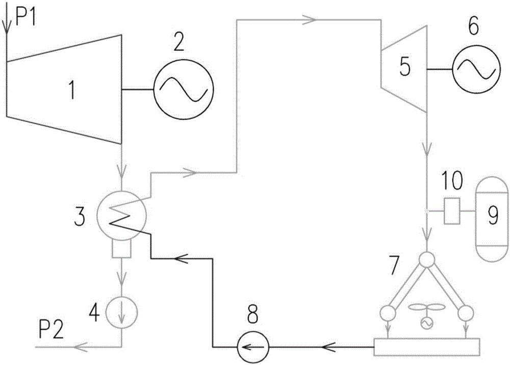
[0035] A combined cycle indirect air cooling system for large coal-fired power plants, such as attached figure 2 shown. The system uses the water vapor Rankine cycle operating at high back pressure as the upper cycle, and the air-cooled Rankine cycle with low freezing point working fluid as the lower cycle to form a high-efficiency combined cycle system, which is equivalent to reducing the temperature of the cold source of the coal-fired unit to close to ambient temperature.

[0036] The circulation system mainly includes main steam turbine 1, main generator 2, condenser 3, condensate pump 4, working medium turbine 5, auxiliary generator 6, air cooling island 7, working medium pump 8, working medium tank 9 and working medium Quality pressure regulating device 10.

[0037] The working process of the circulation system is: the liquid working fluid from the air-cooled island enters the condenser 3 after being pressurized by the working medium pump 8, and is used to condense th...

Embodiment 2

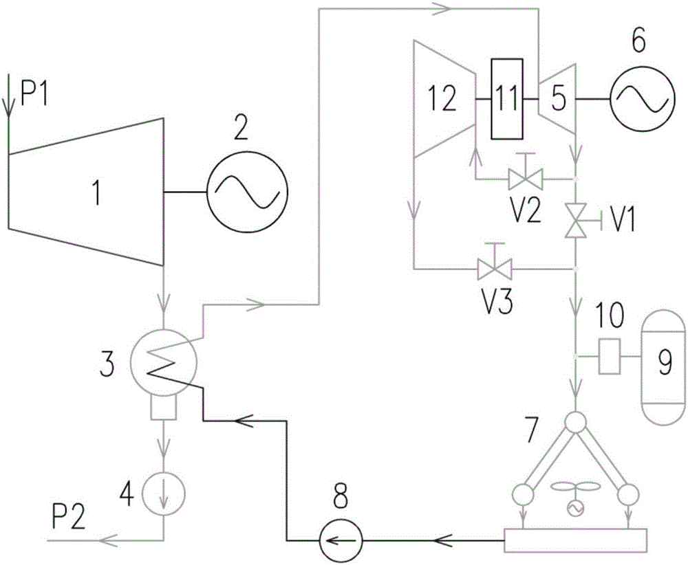
[0040] A combined cycle indirect air cooling system for large coal-fired power plants, such as attached image 3 shown. The system uses the water vapor Rankine cycle operating at high back pressure as the upper cycle, and the air-cooled Rankine cycle with low freezing point working fluid as the lower cycle to form a high-efficiency combined cycle system, which is equivalent to reducing the temperature of the cold source of the coal-fired unit to close to ambient temperature.

[0041] The circulation system mainly includes main steam turbine 1, main generator 2, condenser 3, condensate pump 4, working medium turbine 5, auxiliary generator 6, air cooling island 7, working medium pump 8, working medium tank 9, working medium Mass pressure regulating device 10, clutch 11, low-pressure working fluid turbine 12, and control valves V1, V2, V3.

[0042] The working process of the circulation system is: the liquid working medium from the air-cooling island 7 is pressurized by the wor...

Embodiment 3

[0046] A combined cycle indirect air cooling system for large coal-fired power plants, such as attached Figure 4 shown. The system uses the water vapor Rankine cycle operating at high back pressure as the upper cycle, and the air-cooled Rankine cycle with low freezing point working fluid as the lower cycle to form a high-efficiency combined cycle system, which is equivalent to reducing the temperature of the cold source of the coal-fired unit to close to ambient temperature.

[0047] The circulation system mainly includes main steam turbine 1, main generator 2, condenser 3, condensate pump 4, special working medium turbine 5, auxiliary generator 6, air cooling island 7, working medium pump 8, working medium tank 9, Working medium pressure regulating device 10, circulating fan 13, and control valves V1, V4, V5, V6, V7, V8, V9.

[0048] The working process of the circulation system is: when the ambient temperature is lower than the set temperature B, the control valves V1, V4...


PUM


Abstract

The invention discloses a combined-cycle indirect air cooling system. The combined-cycle indirect air cooling system comprises an air cooling island and a condenser. An outlet end of the air cooling island is connected with a working medium inlet end of the condenser by a working medium pump, a working medium outlet end of the condenser is connected with a working medium turbine and the outlet end of the working medium turbine is connected with an inlet end of the air cooling island. A steam inlet end of the condenser is connected with a main steam turbine. The inlet end of the main steam turbine is connected with a main steam pipeline and a power output shaft of the main steam turbine is connected with a main electric generator. The power output shaft of the working medium turbine is connected with an auxiliary electric generator and a condensed water outlet end of the condenser is connected with a condensed water pipeline by a condensed water pump. A working medium tank is arranged between the outlet end of the working medium turbine and the inlet end of the air cooling island. According to the system, the advantages of the cold sources in the cold areas can be used for lowering the coal consumption rate of an air cooling machine set more efficiently, more environmentally and more reliably.

Description

technical field [0001] The invention belongs to the fields of mechanical engineering and low-temperature waste heat recovery, and relates to a novel high-efficiency air-cooled coal-fired power generation system, in particular to a combined cycle indirect air-cooling system. Background technique [0002] The energy characteristics of "rich coal, poor oil, and little gas" determine that China's coal-based primary energy production and consumption pattern will not change for a long time. In recent years, although the proportion of nuclear power, wind power, and solar power has been increasing, coal-fired power generation is still the absolute main force of my country's electricity production. As of the end of 2015, its installed capacity reached 990 million kilowatts, and its power generation accounted for 73.1% of the total power generation in 2015. However, due to the extremely unbalanced distribution of coal resources and water resources in my country, water resources are e...

Claims


Application Information

Patent Timeline
IPC IPC(8): F01K9/00F01K17/06F01K23/04F01K25/10F01D15/10
CPCF01D15/10F01K9/00F01K9/003F01K17/06F01K23/04F01K25/10
Inventor 王顺森张俊杰颜晓江程上方张磊徐亚涛乔加飞
Owner XI AN JIAOTONG UNIV
Why Eureka
Try Eureka