Power and heat co-supply system based on Stirling engine and power and heat co-supply method of system

A technology of cogeneration and heat storage, which is applied in the direction of combustion methods, heat storage heaters, mechanical equipment, etc., can solve the problems of large fluctuations in power output, unstable residence time, and unstable fuel volume, etc., and achieve power output quality Stability, reduced fly ash carrying amount, and improved practicability

Active Publication Date: 2017-01-25
马加德
View PDF7 Cites 5 Cited by
  • Summary
  • Abstract
  • Description
  • Claims
  • Application Information

AI Technical Summary

Problems solved by technology

[0006] The purpose of the present invention is to solve the problem that the current Stirling machine is applied to the biomass direct-fired power generation boiler, which is easy to cause serious ash and coking at the hot end, and the power generation efficiency drops sharply. It is easy to cause the impact of flue gas concentration and temperature fluctuations on the Stirling machine, and the problem of large fluctuations in power output. A Stirling-based cogeneration system and its method are provided. The Stirling The range of fuel for forestry machines has expanded to energy fields such as coal, biomass (wood, straw, etc.) The power solution of the power island provides a way out; the system also realizes the cogeneration of electricity and heat

Method used


Image

  • Power and heat co-supply system based on Stirling engine and power and heat co-supply method of system

Examples


Embodiment Construction

[0021] The present invention will be further described below in conjunction with the accompanying drawings.

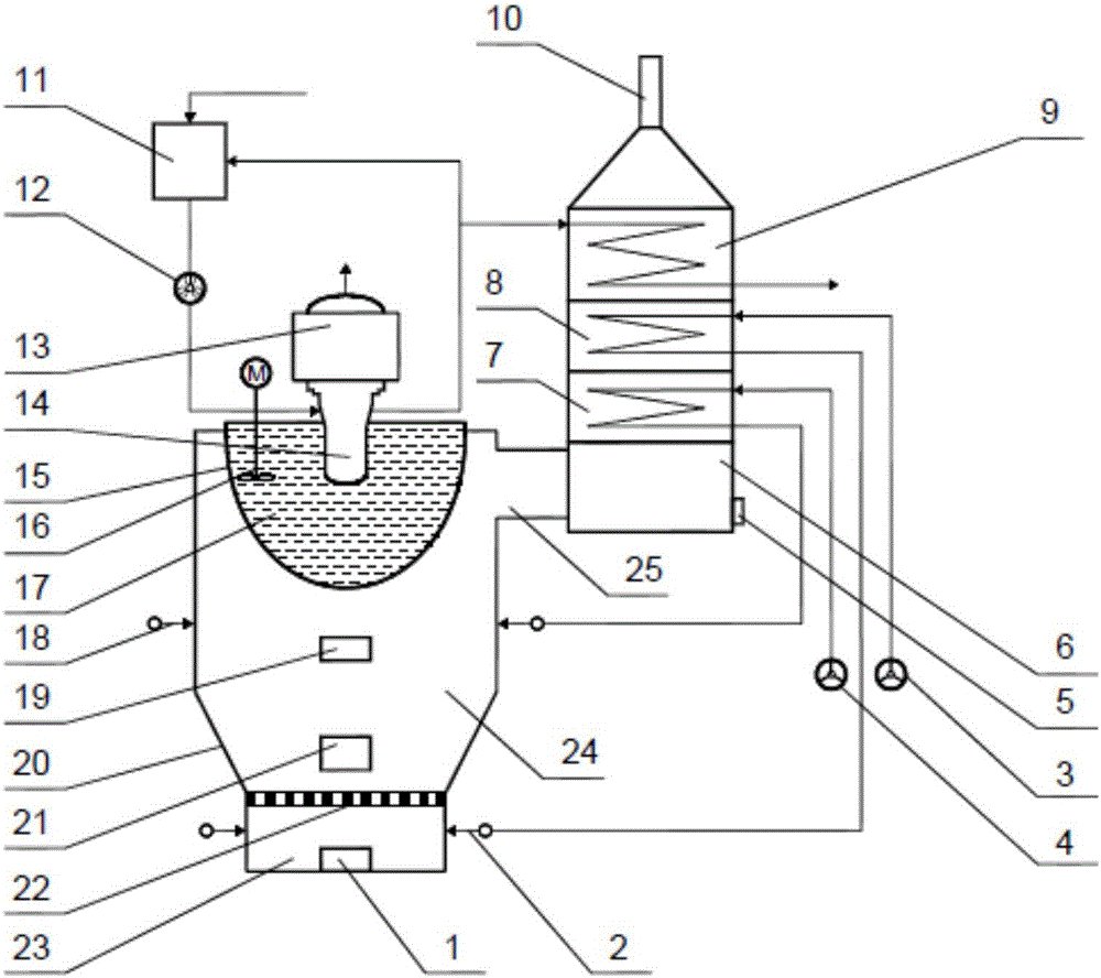
[0022] Such as figure 1As shown, a cogeneration system based on a Stirling machine includes a primary fan 3, a secondary fan 4, an ash collection chamber 6, a secondary air air preheater 7, a primary air air preheater 8, and a coal-saving Device 9, exhaust pipe 10, water tank 11, circulating water pump 12, Stirling machine 13, heat storage pot 15, stirring device 16, combustion furnace 20 and flue 25; combustion furnace 20 includes primary tuyere 2, secondary tuyere 18 , Hearth 24, fire grate 22 and slag collecting chamber 23. The heat storage pot 15 is set on the top of the furnace 24; the fire grate 22 is set on the bottom of the furnace 24; the slag collection chamber 23 is set on the bottom of the fire grate 22; 21 and observation window 19. The top of the side wall of the furnace 24 communicates with the side wall of the ash collection chamber 6 through the flu...


PUM


Abstract

The invention discloses a power and heat co-supply system based on a Stirling engine and a power and heat co-supply method of the system. Grids cannot be laid in a great majority of families in mountainous areas and underdevelopment areas. Biomass combusts in a combustion furnace, molten salt in a heat storage pot is heated, and the high-temperature molten salt heats a hot end of the Stirling engine to drive the Stirling engine to generate power; a circulating water system for cooling a cold end of the Stirling engine flows through the cold end of the Stirling engine and an economizer, waste heat of the two parts is recovered, and hot water at 50-100 DEG C is finally obtained. With the adoption of the system and the method, the problems that the Stirling engine causes severe ash accumulation and coking at the hot end when applied to a biomass direct-combustion power generation boiler and the power generation efficiency is decreased are solved; gradient utilization of energy is realized and the thermal efficiency of the system is high; power and heat co-supply is realized and the energy saving effect is remarkable; the power output quality is stable, the system is very suitable for energy storage and release, and a way is provided for solving the problem about power in power islands in remote areas.

Description

technical field [0001] The invention relates to a combined electricity and heat system based on a Stirling machine and its method, in particular to a Stirling machine-based biomass direct combustion heat storage combined electricity and heat system and a method for the combined electricity and heat. Background technique [0002] Recently, in some areas with special geographical distribution, such as mountainous areas and underdeveloped areas, there are still a large part of household power grids that cannot be laid to households in a short period of time. The reasons why this kind of phenomenon has not been fundamentally solved are as follows: the wind field conditions required for wind power generation are relatively harsh and difficult to apply; the energy density of solar energy is low and the stability is poor, and the power supply of solar power generation is very unstable; clean gas resources cannot Delivered; lack of mineral resources. However, these areas are rich i...

Claims


Application Information

Patent Timeline
Patent Type & Authority Applications(China)
IPC IPC(8): F02G1/043F24H7/00F23L15/00
CPCF02G1/043F23L15/00F24H7/007Y02E20/34
Inventor 马加德王暐李加明张志霄
Owner 马加德
Why Eureka
Try Eureka