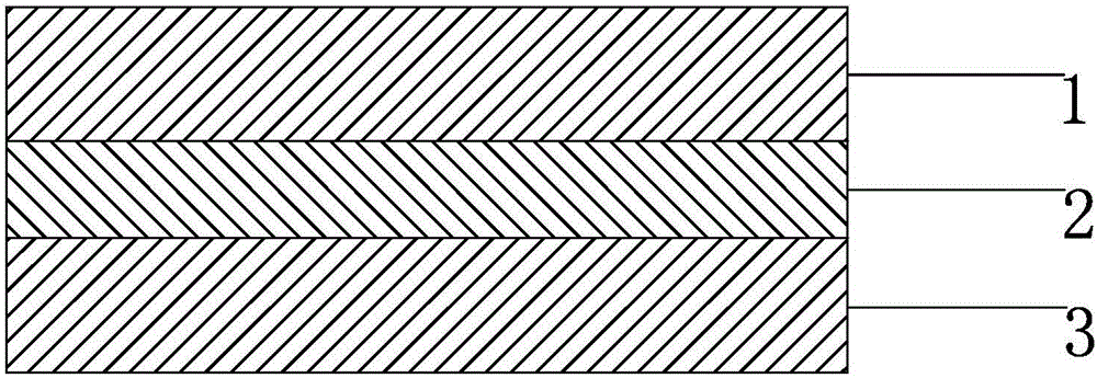
Low driving voltage dimming film and preparation method thereof

A technology of low driving voltage and dimming film, which is applied in the field of dimming film, can solve the problems that the transmittance cannot reach the best and the safety voltage cannot be reached, and achieve excellent photoelectric performance, strong shielding, and low power consumption. Effect

Active Publication Date: 2017-01-25
XIANGTAN UNIV +1
View PDF8 Cites 27 Cited by
  • Summary
  • Abstract
  • Description
  • Claims
  • Application Information

AI Technical Summary

Problems solved by technology

[0005] The dimming film has been in the market for more than 20 years. With the continuous advancement of technology, the transparency and viewing angle of the dimming film have been greatly improved. The working voltage has gradually dropped from the early 110V to 90V, 65V and 48V, but the working voltage It still cannot reach the safe voltage of 36V and below. If you have to use a low voltage of 36V and below, you have to sacrifice the effect of the open state, that is, the transmittance of the open state cannot reach a better state.

Method used


Image

  • Low driving voltage dimming film and preparation method thereof

Examples


specific Embodiment approach 1

[0034] Step a, in a light-shielding environment, mix isobornyl acrylate 25%, isobornyl methacrylate 39%, methacrylate 3%, methacrylate-2-hydroxyethyl 8%, acrylic acid 21%, silane 1% of the joint agent and 3% of 2,4,6-(trimethylbenzoyl) diphenylphosphine oxide are mixed in proportion, and after mixing, they are fully stirred evenly to obtain UV optical adhesive A;

[0035] Step b, mix 40% of UV optical glue with 60% of HPC854200-100 liquid crystal and stir well to obtain mixture B;

[0036] Step c, add 5‰ of 20μm spacers and mix with B, stir well and evenly after defoaming to obtain the final PDLC, waiting for coating construction;

[0037] Step d, the PDLC is sandwiched between two transparent nano-silver conductive films, and rolled to form a liquid crystal film; wherein the nano-silver conductive film is 125 microns thick, with a square resistance of 50Ω, a total light transmittance of 87%, and a haze of 0.8 %;

[0038] Step E, UV curing the liquid crystal film, wherein th...

specific Embodiment approach 2

[0042] Step a, in a light-shielding environment, mix 60% isobornyl methacrylate, 3% hydroxyalkyl methacrylate, 3% 2-hydroxyethyl methacrylate, 26% methacrylic acid, lauryl methacrylate 3% of ester, 2% of silane coupling agent, 3% of 2,4,6-(trimethylbenzoyl) diphenylphosphine oxide are mixed in proportion, and fully stirred evenly after mixing to obtain UV optical adhesive A;

[0043] Step b, mix 45% of UV optical glue with 55% of SLC1717 liquid crystal and stir well to obtain mixture B;

[0044] Step c, add 4‰ of 20μm spacers and mix with B, stir well and evenly after degassing to obtain the final PDLC, waiting for coating construction;

[0045] Step d, the PDLC is sandwiched between two transparent ITO conductive films, and rolled to form a liquid crystal film; wherein the thickness of the ITO conductive film is 188 microns, the square resistance is 50Ω, the total light transmittance is 85%, and the haze is 0.9%;

[0046] Step E, UV curing the liquid crystal film, wherein th...


PUM

PropertyMeasurementUnit
diameteraaaaaaaaaa
electrical resistanceaaaaaaaaaa

Abstract

The invention relates to a low driving voltage dimming film and a preparation method thereof. The preparation method comprises the steps of mixing acrylate, an acrylic monomer, a surfactant and a photoinitiator in a ratio to prepare UV (Ultraviolet) optical cement, mixing the UV optical cement with liquid crystal uniformly, adding 0.1-0.8% of spacer and mixing to prepare PDLC (Polymer Dispersed Liquid Crystal); and sandwiching the PDLC between two transparent conductive films, rolling to form a liquid crystal film, and curing the liquid crystal film by heating or with ultraviolet light, thus forming the dimming film. The obtained low voltage dimming film has the working voltage of 24/36 V and the lower power consumption of 0.5-1.5 W/m<2>, simultaneously has excellent photoelectric performance, and is suitable for metro shielding doors, bathroom partitions, bank partitions and the like.

Description

[0001] 【Technical field】 [0002] The invention belongs to the technical field of dimming films, and in particular relates to a low driving voltage dimming film and a preparation method thereof. [0003] 【Background technique】 [0004] Liquid crystal dimming film is a new type of functional photoelectric film, also known as electronically controlled intelligent dimming film. Through the control of an external electric field, the rapid transformation of the dimming film between colorless transparent and milky white opaque can be realized. Liquid crystal dimming film is widely used, and can be used wherever there is glass. It is usually used in high-end hotel rooms, museums, banks, conference rooms, shop windows, etc. It has privacy protection, space permeability, security and defense, and light adjustment. sex. [0005] The dimming film has been in the market for more than 20 years. With the continuous advancement of technology, the transparency and viewing angle of the dimming...

Claims


Application Information

Patent Timeline
Patent Type & Authority Applications(China)
IPC IPC(8): G02F1/1334C08F220/18C08F220/06C08F220/28C08F220/26
CPCG02F1/1334C08F220/18C08F220/06C08F220/26C08F220/1812C08F220/281
Inventor 吴琴汤立文李唯
Owner XIANGTAN UNIV
Why Eureka
Try Eureka