
Toner Metering Conveyor System

A conveying system and toner technology, applied in conveyors, conveying bulk materials, transportation and packaging, etc., can solve the problems affecting the manufacturing quality of toner fibers, numerical errors, etc., to improve applicability, accuracy, and dyeing. quality effect

Active Publication Date: 2018-10-30
平顶山三信新材料科技有限公司
View PDF9 Cites 0 Cited by
  • Summary
  • Abstract
  • Description
  • Claims
  • Application Information

AI Technical Summary

Problems solved by technology

[0004] The speed of the turntable is controlled by adjusting the speed of the power mechanism through the frequency converter, and the amount of toner can be adjusted. The toner enters the feeding chamber through the toner inlet and fills into the storage hole of the metering turntable. The power mechanism drives the rotating shaft. Rotate to transfer the toner carried in the feed chamber into the discharge chamber, and at the same time transfer the empty storage hole to the feed chamber for storage. When the storage hole full of toner is up and down with the toner outlet Correspondingly, under the action of its own gravity and the compressed air from the first dry compressed air inlet, the toner is blown into the feeding pipe; but the turntable is always in the state of rotation, and the toner will be released under the action of the centrifugal force of the turntable. Cause some toner to adhere to the turntable, and the amount of toner transported each time has been quantified, which will lead to errors in the predetermined value of the toner, thus affecting the manufacturing quality of the toner fiber

Method used


Image

  • Toner Metering Conveyor System
  • Toner Metering Conveyor System
  • Toner Metering Conveyor System

Examples


Embodiment 1

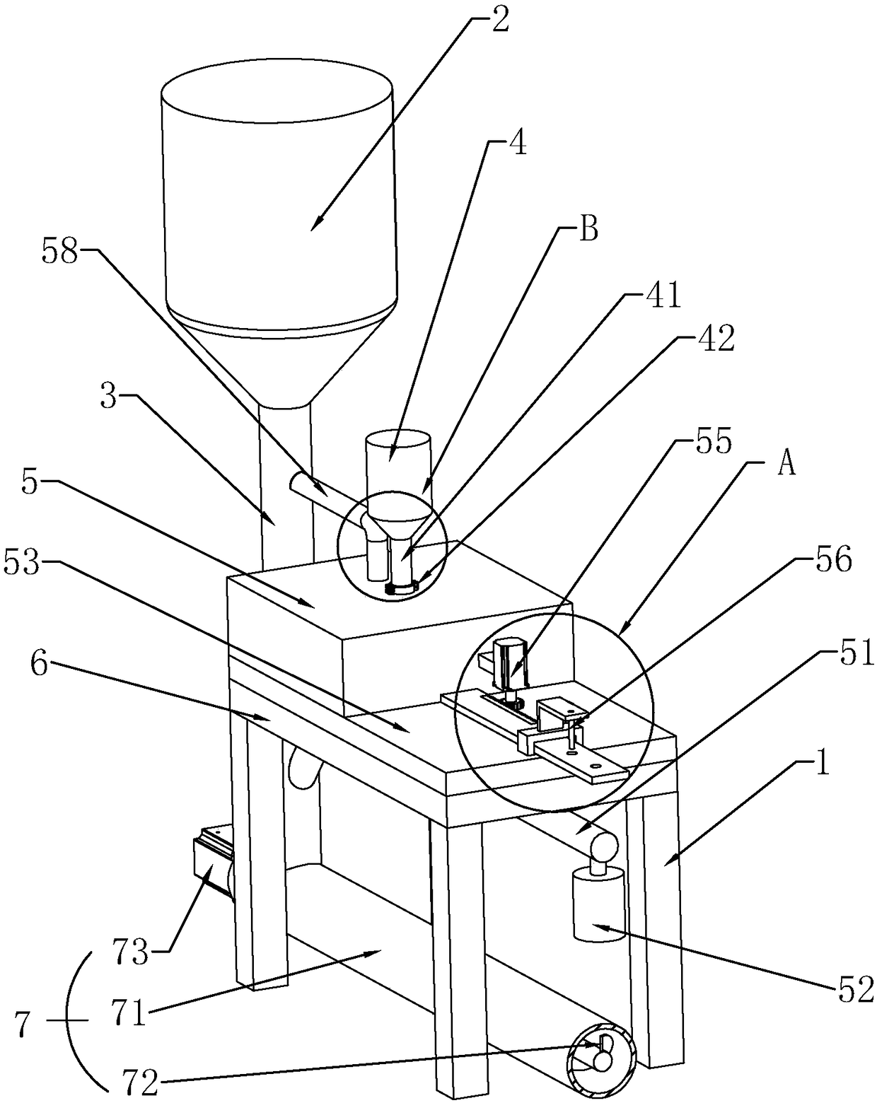
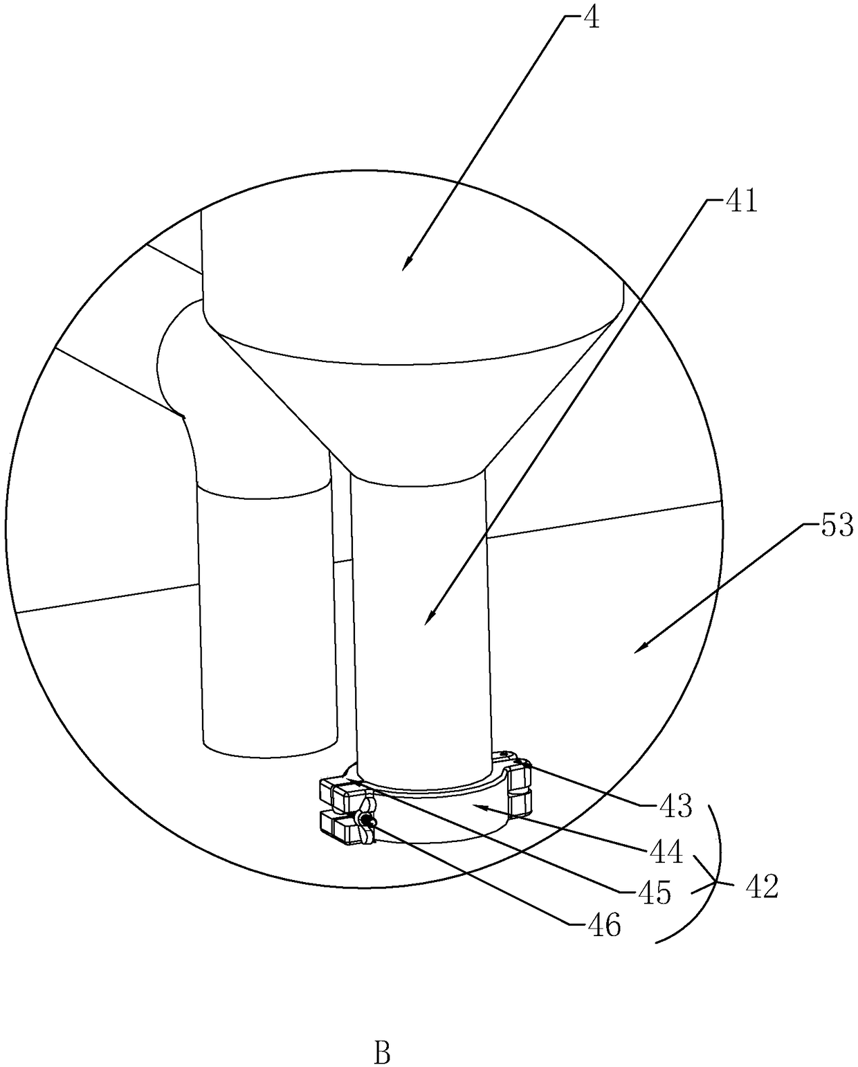
[0039] Embodiment 1: a kind of toner metering delivery system, such as figure 1 As shown, it includes a drying tower 2 arranged on a frame 1 for storing polylactic acid dry slices, a slicing pipeline 3 connected to the drying tower 2 for transporting polylactic acid dry slices, a silo 4 for storing toner, It is used to transport the toner in the silo 4 to the conveying device 5 in the slicing pipeline, and the mixing and melting device 7 connected to the slicing pipeline 3 for conveying the dry chips of polylactic acid and the toner mixed with each other; the silo 4 also It can measure powdery materials such as toner, nano-scale metal powder, nano-scale bamboo toner, titanium dioxide, etc.

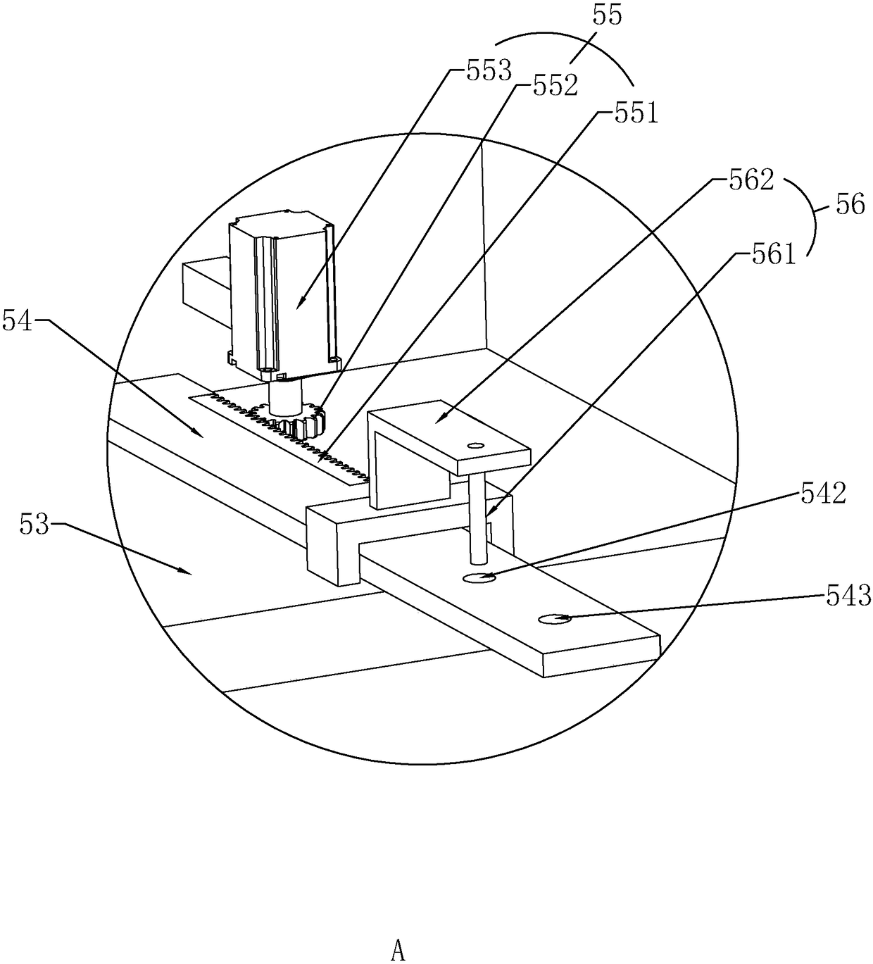
[0040] Such as Figure 4 As shown, wherein, the conveying device 5 includes an airflow passage 51 connected to the slice pipeline 3 at one end, a solenoid valve 52 arranged at the other end of the airflow passage 51 for controlling the delivery of compressed air flow in the airflow passag...

Embodiment 2

[0052] Embodiment 2: a toner metering delivery system, the difference from embodiment 1 is that, as Figure 7 As shown, the drive assembly 55 includes a threaded screw 554 connected to the flashboard 54 and a rotating motor 555 that drives the screw 554 to rotate forward and reverse. The rotating motor 555 is connected to the base plate 53; , so that the screw rod 554 is on the board 54 and is connected with the screw rod 554 of the board 54 to drive the board 54 to slide on the bottom plate 53, and the rotating motor 555 cooperates with the induction component 56 at the same time, so as to adjust the board 54 to be on the bottom board 53 Reciprocating motion effect towards the toner channel 57 direction.

Embodiment 3

[0053] Embodiment 3: a kind of toner metering conveying system, differs from embodiment 1 in that, as Figure 8 As shown, the drive assembly 55 is a hydraulic cylinder 556, the piston of the hydraulic cylinder 556 is fixedly connected to the inserting plate 54, and the sensing assembly 56 controls the reciprocating movement of the piston at intervals, thereby controlling the reciprocating movement of the inserting plate 54 on the base 6 to achieve continuous quantitative The purpose of conveying toner.


PUM


Abstract

The invention discloses a toner metering and conveying system. According to the technical scheme, the toner metering and conveying system is characterized by comprising a drying tower arranged on a rack and used for storing polylactic acid dry slices, a slice pipeline communicated and connected with the drying tower and used for conveying the polylactic acid dry slices, a stock bin used for storing toner, and a conveying device used for conveying the toner in the stock bin into the slice pipeline. The effect of continuously controlling and quantitatively conveying the toner is achieved, and every time the toner in a metering containing hole is conveyed into the slice pipeline to be mixed with the polylactic acid dry slices; and the effects of accurate metering and conveying of the toner and continuous conveying are achieved, and therefore the coloring quality of colored fiber is improved.

Description

technical field [0001] The invention relates to the field of chemical fiber production, more specifically, it relates to a toner metering and conveying system. Background technique [0002] Since fiber dyeing will cause serious water pollution, the production of colored fibers has become the best choice, which can not only reduce production costs. The most important thing is that it can greatly reduce environmental pollution; in the current process of producing colored fibers, the dry toner needs to be granulated into masterbatch before it can enter the spinning screw extruder together with the polylactic acid dry chips, while the current poly The lactic acid masterbatch spinning technology borrows from the chemical fiber masterbatch spinning technology, and uses the color masterbatch slices to be quantitatively sent into the chip drying tower through the masterbatch machine to achieve the corresponding processing procedures for the production of colored fibers. [0003] Th...

Claims


Application Information

Patent Timeline
Patent Type & Authority Patents(China)
IPC IPC(8): B65G65/44B65G53/14B65G65/00
CPCB65G53/14B65G65/005B65G65/44B65G2201/04
Inventor 王维平
Owner 平顶山三信新材料科技有限公司
Learn More