
Pipe jacking construction method of municipal gas pipelines

A technology for gas pipelines and construction methods, which is applied in pipeline laying and maintenance, pipes/pipe joints/fittings, mechanical equipment, etc. It can solve the problems of many leakage points, damage, poor corrosion resistance of pipelines, etc., to prevent ground subsidence, The effect of improving work efficiency and increasing the strength of the carbon layer

Inactive Publication Date: 2017-02-15
安顺集团建设有限公司
View PDF5 Cites 2 Cited by
  • Summary
  • Abstract
  • Description
  • Claims
  • Application Information

AI Technical Summary

Problems solved by technology

The main problems are: the welding quality of pipelines on the construction site cannot be monitored effectively, the quality of welds cannot be guaranteed, the number of pipeline connections is large, and there are many potential leakage points, and the pipelines and equipment are heavy and inconvenient to install; the technical level of construction personnel is high. , the installation quality control is difficult; the pipeline is easy to damage the anti-corrosion layer or galvanized layer during transportation and construction; the pipeline has poor corrosion resistance, short service life, and large capital and labor costs for later maintenance, which cannot guarantee the safety of the gas pipeline system sex and reliability
For the butt connection of gas pipelines under special climatic conditions, it is necessary to ensure the performance stability of the interface, and also to increase its strength to ensure that it is not affected by external conditions; the existing gas pipeline butt welding interface is exposed to the outside without protective measures. Often damaged in advance under special climatic conditions

Method used


Image

  • Pipe jacking construction method of municipal gas pipelines

Examples


Embodiment 1

[0028] A pipe jacking construction method of a municipal gas pipeline in this embodiment comprises the following steps:

[0029] (1) According to the given control pile position in the design, use theodolite to release the crossing axis, and determine the crossing center pile and construction belt sideline pile, and sprinkle gray lines, and release the position and size of the originating well at the same time when setting out the lines.

[0030] (2) Level the position of the caisson given in the design, and then prefabricate the caisson as a whole on the ground according to the requirements of the design drawings, and construct the sending well and the receiving well at the same time.

[0031] (3) When the strength of the reinforced concrete caisson poured on site reaches the design requirements after maintenance, the caisson is sunk evenly, and the caisson operation is stopped after reaching the design elevation; A dewatering well is evenly spaced at 3m, so that the water le...

Embodiment 2

[0041]The method of this embodiment is the same as that of Embodiment 1, the difference is that: the polypropylene foam material and the outer surface of the outer tube are coated with an anti-icing adhesion emulsion, and the components by weight of the polypropylene foam material of this embodiment are composed of: Acrylic resin: 106 parts, nucleating agent: 7 parts, antioxidant: 2 parts, lubricant: 1.6 parts, filler: 18 parts, nano silica: 14 parts, methyl hydrogen silicone oil: 66 parts, hydroxyl poly Dimethicone: 12 parts, Vinyltrimethoxysilane: 12 parts, Ammonium Polyphosphate: 6 parts, Alkyl Dimethicone: 13 parts, Polyisobutylene: 12 parts, Alkylphenol poly Oxyethylene ether: 8 parts, reactive diluent: 5.6 parts, coupling agent: 1.6 parts, leveling agent: 3.4 parts; the particle diameter of the nano silicon dioxide is 25nm. The nucleating agent is one or more mixtures of silicon dioxide, calcium carbonate, carbon black, graphite, talcum powder, and inorganic oxides; the ...

Embodiment 3

[0044] The method of this embodiment is the same as that of Embodiment 1, the difference is that: the polypropylene foam material and the outer surface of the outer tube are coated with an anti-icing adhesion emulsion, and the components by weight of the polypropylene foam material of this embodiment are composed of: Acrylic resin: 107 parts, nucleating agent: 8 parts, antioxidant: 3 parts, lubricant: 1.7 parts, filler: 19 parts, nano silica: 15 parts, methyl hydrogen silicone oil: 67 parts, hydroxyl poly Dimethicone: 13 parts, Vinyltrimethoxysilane: 13 parts, Ammonium Polyphosphate: 7 parts, Alkyl Dimethicone: 15 parts, Polyisobutylene: 13 parts, Alkylphenol poly Oxyethylene ether: 9 parts, reactive diluent: 5.7 parts, coupling agent: 1.7 parts, leveling agent: 3.5 parts; the particle diameter of the nano silicon dioxide is 30nm. The nucleating agent is one or more mixtures of silicon dioxide, calcium carbonate, carbon black, graphite, talcum powder, and inorganic oxides; the...


PUM


Abstract

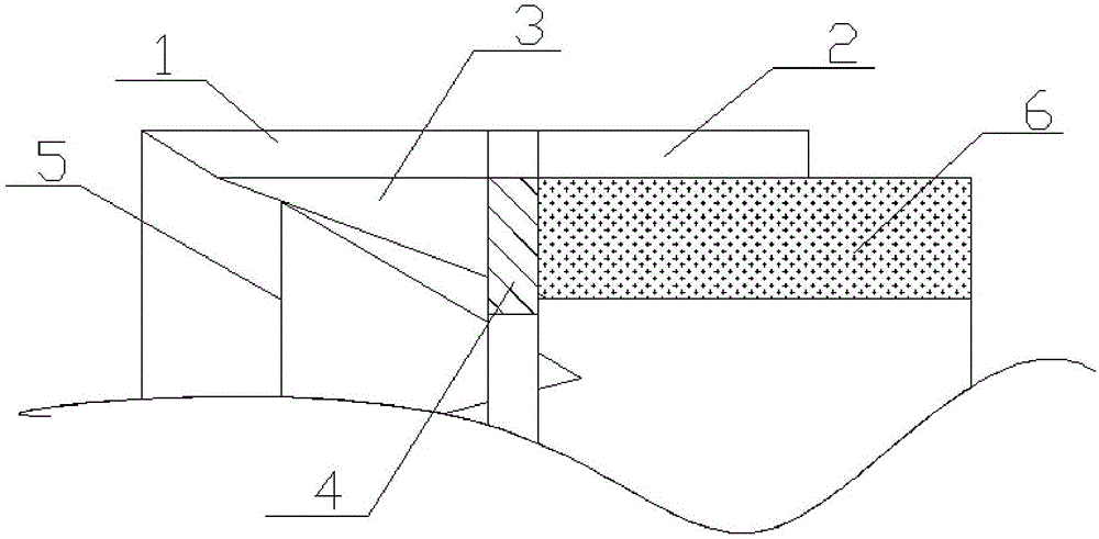
A pipe jacking construction method of municipal gas pipelines includes the steps that firstly, measurement and paying-off are conducted; secondly, an open caisson is constructed; thirdly, after the open caisson meets design requirements after maintenance, the open caisson evenly sinks and reaches designed elevation, and open caisson work stops; fourthly, installation of a jacking device and back wall treatment are conducted; fourthly, foot blades are installed, wherein the foot blades are symmetrically arranged at the top ends of sleeves, and each foot blade comprises a shielding plate, a tail plate, a ribbed plate, an annular beam and a fixing frame; sixthly, pipe jacking is conducted; seventhly, crossing pipe sections are welded, and then a reinforcing pipe is arranged on the butt joint of two gas pipelines, wherein the reinforcing pipe comprises an outer pipe and a polypropylene foaming material, the butt joint portion of the two gas pipelines is sleeved with the outer pipe, and the portion between the inner wall of the outer pipe and the outer walls of the gas pipelines in butt joint is filled with the polypropylene foaming material. By means of the foot blades, jacking of the sleeves are benefited, resistance is reduced, and the sleeves do not deviate during jacking and move along the pipelines; structural performance of the joint of the two adjacent gas pipelines in butt joint can be improved.

Description

technical field [0001] The invention relates to the technical field of gas pipeline construction, in particular to a pipe jacking construction method of a municipal gas pipeline. Background technique [0002] The construction of gas pipelines is mainly steel pipelines and PE pipelines. The construction methods used in the gas pipeline system are on-site measurement, on-site processing of pipeline threads, welding or threading, and anti-corrosion or painting operations after completion. The pipe fittings and joints used are all standard parts, which can be modified and manufactured on site according to specific requirements. The main problems are: the welding quality of pipelines on the construction site cannot be monitored effectively, the quality of welds cannot be guaranteed, the number of pipeline joints is large, and there are many potential leakage points, and the pipelines and equipment are heavy and inconvenient to install; the technical level of construction personne...

Claims


Application Information

Patent Timeline
Patent Type & Authority Applications(China)
IPC IPC(8): F16L1/028
CPCF16L1/028
Inventor 陈宏张斌缪逸民胡为庚史国栋
Owner 安顺集团建设有限公司
Learn More