Full-automatic silicon single-crystal rod rolling and grinding integrated equipment

A fully automatic technology for single crystal silicon rods, applied in grinding/polishing equipment, metal processing equipment, grinders, etc. Silicon ingot processing size is limited, and the degree of automation of the roller mill is low, so as to save manpower and logistics costs, reduce processing pollution and noise on the workshop environment, and speed up the effect.

Active Publication Date: 2017-03-08
ZHEJIANG JINGSHENG MECHANICAL & ELECTRICAL
View PDF9 Cites 7 Cited by
  • Summary
  • Abstract
  • Description
  • Claims
  • Application Information

AI Technical Summary

Problems solved by technology

[0003] At present, most domestic semiconductor manufacturers still use the general-purpose grinding machine to be transformed into a cylindrical rolling machine tool. This type of machine tool needs to be manually completed in multiple times for loading, centering, and crystal orientation detection of single crystal silicon rods, and The accuracy is not very high
The monocrystalline silicon ingot rolling mill widely used in the market has the following disadvantages and deficiencies: the loading of the monocrystalline silicon ingot needs to be carried by the equipment manually, and placed in the middle of the head and tail seat clamping workbench; the monocrystalline silicon ingot and the head The coaxiality of the tailstock clamping table is centered by manual

Method used


Image

  • Full-automatic silicon single-crystal rod rolling and grinding integrated equipment
  • Full-automatic silicon single-crystal rod rolling and grinding integrated equipment
  • Full-automatic silicon single-crystal rod rolling and grinding integrated equipment

Examples


Embodiment Construction

[0036] The following examples can make those skilled in the technical field understand the present invention more comprehensively, but do not limit the present invention in any way.

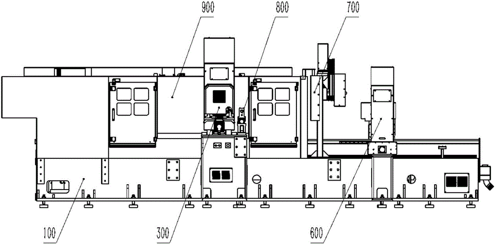
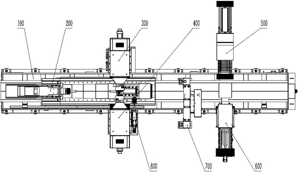
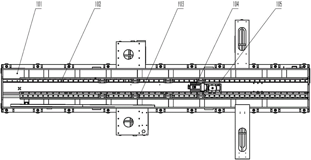
[0037] The fully automatic monocrystalline silicon rod rolling and grinding integrated equipment of the present invention includes a large chassis 100 for carrying; the large chassis 100 is in the shape of a long strip, and two parallel main rails 102 are arranged on its surface along the length direction The grinding table assembly 200 is movably installed on the two main rails 102, and the main drive motor 104 realizes the movement along the main rails 102 through the driving connection mechanism; platform: two platforms are located in the middle of the large chassis 100 and are arranged oppositely, one of which carries the coarse grinding power head assembly 300, and the other carries the fine grinding power head assembly 400; the other two platforms are located at one end of the large chassis ...


PUM


Abstract

The invention relates to silicon single-crystal rod machining equipment and aims to provide full-automatic silicon single-crystal rod rolling and grinding integrated equipment which comprises a long-strip-shaped large bottom frame. Two parallel main guide rails are arranged on the surface of the large bottom frame in the length direction. A grinding work table assembly is movably installed on the two main guide rails, and a main driving motor drives a connecting mechanism so that the grinding work table assembly can move along the main guide rails. Four platforms used for bearing are arranged on the two sides of the large bottom frame and used for bearing a coarse grinding power head assembly, a fine grinding power head assembly, a feeding mechanical hand assembly and a centering mechanical hand assembly correspondingly. A crystal orientation detecting device and a radius detecting unit are further arranged on the large bottom frame. The machining range of the crystal rod rolling and grinding equipment is widened greatly, the machining ability of the crystal rod rolling and grinding equipment is improved greatly, and a silicon bar can be centered automatically; the machining efficiency is improved, and cost of manpower and logistics is saved; long and stable high-precision operation of the equipment can be ensured; and the production noise is remarkably reduced, no organic matter emission is generated, less waste is generated, and the ecological environment is protected.

Description

technical field [0001] The invention belongs to the field of single crystal silicon rod processing equipment, and in particular relates to a full-automatic single crystal silicon rod rolling and grinding integrated equipment. Background technique [0002] As an important semiconductor material, silicon single crystal has good electrical properties and thermal stability. Since it was discovered and utilized by people in the 1960s, it has rapidly replaced germanium single crystal as the main material of semiconductors. Silicon material has become the most widely used semiconductor material because of its high temperature resistance and radiation resistance, and is especially suitable for making high-power devices. Most integrated circuit semiconductor devices are made of silicon materials. Among the methods for preparing silicon single crystals with good performance, the Czochralski method for growing silicon single crystals has relatively simple equipment and processes, and i...

Claims


Application Information

Patent Timeline
IPC IPC(8): B24B27/00B24B41/02B24B47/04B24B47/20B24B49/00B24B55/00B24B55/06
CPCB24B27/0076B24B41/02B24B47/04B24B47/20B24B49/00B24B55/00B24B55/06
Inventor 曹建伟沈文杰严浩傅林坚吴兵兵何守龙谢龙辉王凯邱敏秀
Owner ZHEJIANG JINGSHENG MECHANICAL & ELECTRICAL
Why Eureka
Try Eureka