Method for producing clean diesel fuel through high-sulfur-nitrogen poor-quality diesel fuel

A low-quality diesel, high-sulfur technology, applied in chemical instruments and methods, processing hydrocarbon oil, petroleum industry, etc., can solve the problems of increasing equipment, difficulty in operation, and increasing cost, and achieves mild conditions, simple operation, and low cost. Effect

Active Publication Date: 2017-04-05
CHINA PETROLEUM & CHEM CORP +1
View PDF9 Cites 5 Cited by
  • Summary
  • Abstract
  • Description
  • Claims
  • Application Information

AI Technical Summary

Problems solved by technology

[0005] For example, CN1173012C discloses a method for deep desulfurization and dearomatization of diesel oil. The method adopts non-precious metal catalysts to remove sulfur and aromatics content in diesel raw materials under medium pressure. However, a high-pressure hydrogen stripping tower is set in the method, and the investment cost and high operating costs
CN1415706A discloses a method for producing low-sulfur, low-aromatic clean diesel, which can produce low-sulfur, low-aromatic clean diesel, but the pressure of the catalytic stripping reactor is used in the method, and the operation is difficult; The structure of the reactor is complex, the engineering design is

Method used


Image

  • Method for producing clean diesel fuel through high-sulfur-nitrogen poor-quality diesel fuel
  • Method for producing clean diesel fuel through high-sulfur-nitrogen poor-quality diesel fuel

Examples


Embodiment 1

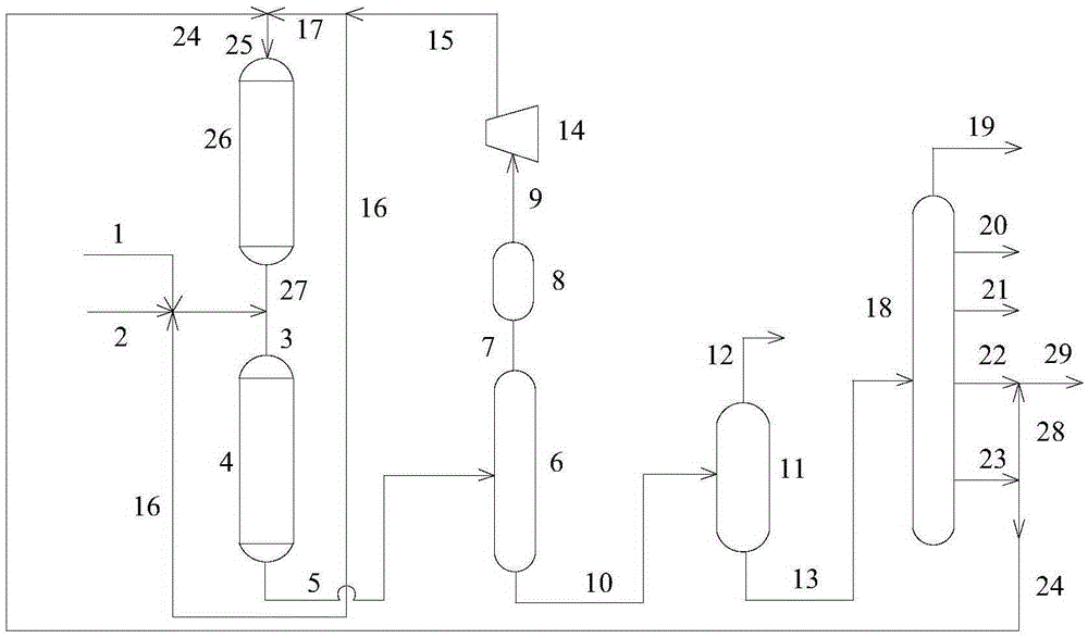
[0102] This embodiment adopts figure 1 The process flow method shown is carried out. and specifically:

[0103] The raw material oil A and the reaction product of the second hydrogenation reaction zone enter the first hydrogenation reaction zone together with new hydrogen and recycled hydrogen, and react under the action of the hydrogenation protection agent and the hydrofinishing catalyst I, and the reaction product is passed through After cooling and separation, a liquid phase and a hydrogen-containing gas phase are obtained, and the hydrogen-containing gas phase is separated and removed to obtain circulating hydrogen; the obtained liquid phase enters a fractionation system and is cut to obtain dry gas, liquefied petroleum gas, petroleum Naphtha fraction, refined diesel fraction and heavy diesel fraction, wherein the refined diesel fraction and the heavy diesel fraction have a cut point of 320°C, 75% by weight (relative to the total weight of all produced heavy diesel fract...

Embodiment 2

[0106] This embodiment adopts figure 1 The process flow method shown is carried out. and specifically:

[0107] The raw material oil A and the reaction product of the second hydrogenation reaction zone enter the first hydrogenation reaction zone together with new hydrogen and recycled hydrogen, and react under the action of the hydrogenation protection agent and the hydrofinishing catalyst I, and the reaction product is passed through After cooling and separation, a liquid phase and a hydrogen-containing gas phase are obtained, and the hydrogen-containing gas phase is separated and removed to obtain circulating hydrogen; the obtained liquid phase enters a fractionation system and is cut to obtain dry gas, liquefied petroleum gas, petroleum Naphtha fractions, refined diesel fractions and heavy diesel fractions, wherein the refined diesel fraction and the heavy diesel fraction have a cut point of 300°C, 50% by weight (relative to the total weight of all produced heavy diesel fr...

Embodiment 3

[0110] This embodiment adopts figure 1 The process flow method shown is carried out. and specifically:

[0111] The raw material oil A and the reaction product of the second hydrogenation reaction zone enter the first hydrogenation reaction zone together with new hydrogen and recycled hydrogen, and react under the action of the hydrogenation protection agent and the hydrofinishing catalyst I, and the reaction product is passed through After cooling and separation, a liquid phase and a hydrogen-containing gas phase are obtained, and the hydrogen-containing gas phase is separated and removed to obtain circulating hydrogen; the obtained liquid phase enters a fractionation system and is cut to obtain dry gas, liquefied petroleum gas, petroleum Naphtha fraction, refined diesel fraction and heavy diesel fraction, wherein the refined diesel fraction and the heavy diesel fraction have a cut point of 330°C, 90% by weight (relative to the total weight of all produced heavy diesel fract...


PUM


Abstract

The invention relates to the field of oil refining and discloses a method for producing clean diesel fuel. The method comprises the following steps that a reaction is conducted in a first hydrogenation reaction area after the high-sulfur-nitrogen poor-quality diesel fuel and reaction products in a second hydrogenation reaction area are mixed with hydrogen-containing substance flow,hydrogenation and refinement reaction products are obtained and then subjected to separation and fractional distillation, and refined diesel fuel cut fraction and heavy diesel fuel cut fraction are obtained; at least part of the heavy diesel fuel cut fraction and hydrogen containing substance flow are led into the second hydrogenation reaction area, and products in the second hydrogenation reaction area are led into the first hydrogenation reaction area; and the refined diesel fuel cut fraction and the rest of the heavy diesel fuel cut fraction are mixed to obtain the clean diesel fuel, wherein the sulfur content of the high-sulfur-nitrogen poor-quality diesel fuel is higher than 5000 [mu]g/g, the nitrogen content of the high-sulfur-nitrogen poor-quality diesel fuel is higher than 700 [mu]g/g, and the arene content of the high-sulfur-nitrogen poor-quality diesel fuel is higher than 50% by weight. According to the method for producing the clean diesel fuel through the high-sulfur-nitrogen poor-quality diesel fuel, conditions are moderate, operating is easy, cost is low, and the clean diesel fuel with the sulfur content, the nitrogen content and the arene content meeting the Euro V standard and the cetane number improved by 10 units or over can be produced.

Description

technical field [0001] The invention relates to the field of petroleum processing, in particular to a method for producing clean diesel from high-sulfur-nitrogen low-quality diesel. Background technique [0002] In recent years, with the continuous increase of car ownership and the rapid development of diesel engines, the demand for vehicle fuel, especially vehicle diesel, is increasing. At the same time, with the enhancement of people's awareness of environmental protection, countries around the world have enacted more stringent environmental protection regulations to strictly control the indicators of vehicle diesel oil. The use of diesel also puts forward higher requirements in terms of density, aromatic content and cetane number. For example, the Euro IV emission standard implemented by the European Union since 2005 stipulates that the sulfur content of diesel for vehicles shall be less than 50 μg / g, the content of polycyclic aromatic hydrocarbons shall not be higher th...

Claims


Application Information

Patent Timeline
IPC IPC(8): C10G67/02B01J27/19B01J23/888
Inventor 王福江高晓冬任亮梁家林
Owner CHINA PETROLEUM & CHEM CORP
Why Eureka
Try Eureka