Excited Raman spectrum imaging system based on fast scanning optical path

A stimulated Raman, fast scanning technology, applied in Raman scattering, spectrometry/spectrophotometry/monochromator, material excitation analysis, etc. To quickly measure the spectrum, slow speed and other problems, to achieve the effect of improving detection sensitivity, easy operation, and eliminating spectral errors

Active Publication Date: 2017-05-10
FUDAN UNIV
View PDF5 Cites 15 Cited by
  • Summary
  • Abstract
  • Description
  • Claims
  • Application Information

AI Technical Summary

Problems solved by technology

However, the conventional method of adjusting the position of the optical delay line is to move the position of the mirror by means of mechanical translation, which is slow and cannot detect two or more Raman vibration frequencies in real time.
For fast-moving objects that require two-color or multi-color imaging, multiple monochrome images for different Raman peaks will inevitably introduce errors when they are combined into one multi-color image
Moreover, the acquisition of stimulated Raman spectra is also limited by the moving speed of the optical delay line, which cannot achieve the effect of fast measurement of spectra

Method used


Image

  • Excited Raman spectrum imaging system based on fast scanning optical path
  • Excited Raman spectrum imaging system based on fast scanning optical path
  • Excited Raman spectrum imaging system based on fast scanning optical path

Examples


Embodiment Construction

[0016] The steps to build and test a two-color stimulated Raman imaging system are as follows:

[0017] (1) Optical path construction.

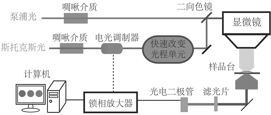
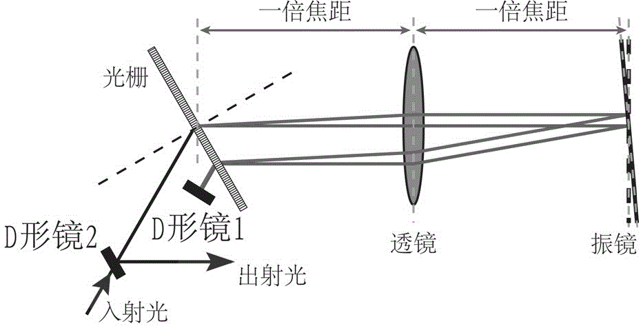
[0018] Such as figure 1 As shown, the multicolor stimulated Raman imaging system proposed by the present invention is based on the hyperspectral stimulated Raman imaging system. The pulses of pump light and Stokes light, both of which are linearly polarized, are time-stretched by a chirped medium. The Stokes light is modulated by an electro-optic modulator at a specific modulation frequency and then passes through a rapidly changing optical path unit. Finally, it is combined with the pump light through a dichroic mirror and directed into the microscope. After the two laser beams interact on the sample, they are filtered by a short-pass filter, and the intensity of the remaining pump light is detected by the photodiode and sent to the lock-in amplifier for analysis; the analysis frequency of the lock-in amplifier is related to the electro-o...


PUM


Abstract

The invention belongs to the technical field of non-linear optical imaging and particularly relates to an excited Raman spectrum imaging system based on a fast scanning optical path. A galvanometer scanning unit capable of quickly generating optical path delaying and the excited Raman spectrum imaging system are combined together, and the excited Raman spectrum imaging system based on the fast scanning optical path is simple in structure, low in modification cost and easy to implement. Since the excited Raman spectrum imaging system can quickly generate the optical path delaying required by a spectral focusing method, excited Raman spectrums of a sample can be quickly collected, the spectrums collected many times can be averaged, so that the signal-to-noise ratio can be greatly improved, and thus the detection sensitivity is improved; target objects of various ingredients are detected in real time; and when Raman spectrums of two target objects in a measured sample overlap (such as lipid and protein), spectral errors caused by movement of the sample are eliminated. According to the system, the excited Raman spectrums can be quickly collected, and simultaneous imaging can be performed according to multiple Raman vibrational peaks.

Description

technical field [0001] The invention belongs to the technical field of nonlinear optical imaging, and in particular relates to an improved stimulated Raman spectrum imaging system, which can realize fast stimulated Raman spectrum acquisition and simultaneously image multiple Raman vibration peaks at the same time system. Background technique [0002] Stimulated Raman imaging technology is a new non-linear optical imaging method. With many advantages such as high signal intensity, no spectral distortion, and linear relationship between signal intensity and analyte concentration, stimulated Raman imaging has become more and more popular in recent years. Technology has developed rapidly and is widely used in biomedical detection and imaging, biochemical analysis and other fields. [0003] Stimulated Raman scattering is an organic combination of Raman scattering and stimulated radiation technology, which requires two beams of high-energy-density pulsed lasers with different fre...

Claims


Application Information

Patent Timeline
Patent Type & Authority Applications(China)
IPC IPC(8): G01N21/65G01J3/44
CPCG01J3/44G01N21/65G01N2021/655
Inventor 季敏标贺若愚徐永奎刘知平
Owner FUDAN UNIV
Why Eureka
Try Eureka