Method and apparatus for flue gas desulfurization and sulfuric acid production

A flue gas and sulfuric acid technology, which is applied in the field of flue gas desulfurization and sulfuric acid production, can solve the problems of high operating cost, difficult separation, large ozone consumption and power consumption, etc., and achieves high utilization rate, high desulfurization efficiency, and increased gas The effect of liquid mass transfer effect

Active Publication Date: 2017-05-17
SINOPEC DALIAN RES INST OF PETROLEUM & PETROCHEMICALS CO LTD +1
View PDF10 Cites 3 Cited by
  • Summary
  • Abstract
  • Description
  • Claims
  • Application Information

AI Technical Summary

Problems solved by technology

This technology consumes a lot of ozone and electricity, and the operating cost is high, and both sulfuric acid and nitric acid are strong acids, which are difficult to separate.

Method used


Image

  • Method and apparatus for flue gas desulfurization and sulfuric acid production
  • Method and apparatus for flue gas desulfurization and sulfuric acid production
  • Method and apparatus for flue gas desulfurization and sulfuric acid production

Examples


Embodiment 1

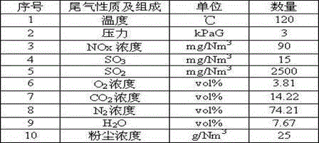
[0044] The flue gas composition of a catalytic cracking catalyst regenerated is shown in Table 1.

[0045] Table 1 Composition of flue gas regenerated from a catalytic cracking catalyst.

[0046]

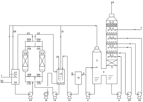
[0047] Operating conditions of the present invention: (1) The dedusting and quenching tower adopts a Venturi deduster, and the liquid-gas ratio is 3.0L / m 3 ; (2) Desulfurization tower deep dust removal unit 5-1 is filled with fillers, the desulfurization unit is 2-stage, all adopt spray absorption, and the liquid-gas ratio is 3.0L / m 3 ; (3) The absorbent of the washing unit of the desulfurization tower is supplemented with fresh water, and the liquid-gas ratio is 5.0L / m 3 (4) A microporous aeration hose is arranged in the oxidation tank to disperse the air in the liquid phase in the form of micropores. The amount of air added is 4 times the amount of the liquid phase (volume) in the oxidation tank, Add ferric sulfate solution, where Fe 3+ The mass concentration is 3.0%; (5) Th...

Embodiment 2

[0050] The flue gas composition of adsorbent regeneration in a S zorb unit is shown in Table 2.

[0051] Table 2 Composition of flue gas from adsorbent regeneration in a certain S-zorb device.

[0052]

[0053] The operating conditions of the present invention: (1) The dedusting and quenching tower adopts turbulence as the mass transfer component, and the liquid-gas ratio is 7.0L / m 3 ; (2) The desulfurization tower deep dust removal unit 5-1 is filled with packing, the desulfurization unit is 4 levels, all adopt spray absorption, and the liquid-gas ratio is 5.0 L / m 3 ; (3) The absorbent of the washing unit of the desulfurization tower is supplemented with fresh water, and the liquid-gas ratio is 3.0 L / m 3 (4) A microporous aeration hose is arranged in the oxidation tank to disperse the air in the liquid phase in the form of micropores. The amount of air added is 5 times the amount of the liquid phase (volume) in the oxidation tank, Add iron sulfate solution, and auxiliary...

Embodiment 3

[0056] The flue gas composition of a coal-fired boiler is shown in Table 3.

[0057] Table 3 Flue gas composition of a coal-fired boiler.

[0058]

[0059] Operating conditions of the present invention: (1) The dedusting and quenching tower adopts turbulence, and the liquid-gas ratio is 8.0 L / m 3 ; (2) The desulfurization tower deep dust removal unit 5-1 is filled with packing, the desulfurization unit is 3 levels, all adopt spray absorption, and the liquid-gas ratio is 3.0 L / m 3 ; (3) The absorbent of the washing unit of the desulfurization tower is supplemented with fresh water, and the liquid-gas ratio is 5.0 L / m 3(4) A microporous aeration hose is arranged in the oxidation tank to disperse the air in the liquid phase in the form of micropores. The amount of air added is 6 times the liquid phase (volume) in the oxidation tank, and at the same time Add iron sulfate solution, and auxiliary oxidant H 2 o 2 , where Fe 3+ Mass concentration 3.0%, H 2 o 2 The concentrat...


PUM

PropertyMeasurementUnit
particle diameteraaaaaaaaaa
water contentaaaaaaaaaa

Abstract

The present invention discloses a method and an apparatus for flue gas desulfurization and sulfuric acid production. The method comprises that (1) flue gas is subjected to heat exchange through a sulfuric acid storage tank, and then the obtained flue gas enters a dust removing quenching tower and is subjected to primary dust removing cooling; (2) the cooled flue gas enters a desulfurization tower and sequentially passes through a deep dust removing unit, a desulfurization unit and a water washing unit from bottom to top; (3) in the water washing unit, the SOx in the flue gas is absorbed with fresh water, the liquid phase overflows and sequentially passes through the desulfurization unit and the deep dust removing unit, the obtained liquid phase enters the dust removing quenching tower to obtain a rich absorption liquid, solid-liquid separation is performed, and the gas phase is discharged in atmosphere after defogging; and (4) the rich absorption liquid being subjected to solid waste separation is discharged into an oxidation tank, the liquid phase enters a regeneration tower, the Fe<3+>/Fe<2+> in the liquid phase is removed, and the obtained liquid phase enters the sulfuric acid storage tank in the form of dilute sulfuric acid. With the method and the apparatus of the present invention, the SO2 in the flue gas can be absorbed and concentrated, and can be oxidized into the sulfuric acid so as to produce the high concentration sulfuric acid, the purified flue gas can meet the national or local relevant standard requirements, and the method and the apparatus are suitable for the recovery treatment of flue gas containing various concentrations of sulfur dioxide.

Description

technical field [0001] The invention belongs to the technical field of environmental protection, and in particular relates to a method and a device for flue gas desulfurization and sulfuric acid production. Background technique [0002] Since 2003, my country's SO 2 The total emissions have remained high. In 2014, my country's SO 2 The total emissions were 19.744 million tons, which was below 20 million tons for the first time since 2003. Although the goal of reducing sulfur dioxide by 10% during the "Eleventh Five-Year Plan" period in my country has been achieved, the current acid rain pollution area in China (accounting for 30% of the country's land area) is still expanding, and is changing from "sulfuric acid type" to "sulfuric acid nitric acid compound type" " Transformation. Each year due to acid rain and SO 2 Pollution has caused economic losses of more than 100 billion yuan in crops, forests and human health, and the control of sulfur dioxide emissions cannot be ig...

Claims


Application Information

Patent Timeline
Patent Type & Authority Applications(China)
IPC IPC(8): B01D53/14B01D53/18B01D47/06B01D47/00B01D47/14B01D50/00C01B17/76C01B17/80
CPCB01D47/00B01D47/06B01D47/14B01D50/00B01D53/1406B01D53/1418B01D53/1481B01D53/18B01D2247/107B01D2252/103B01D2257/302B01D2258/02C01B17/76C01B17/80
Inventor 王明星李欣阮宗林王岩姜阳
Owner SINOPEC DALIAN RES INST OF PETROLEUM & PETROCHEMICALS CO LTD
Why Eureka
Try Eureka