
Silicon wafer lifting device and control method thereof

A technology of a pulling device and a control method, which is applied in the field of silicon wafer pulling device and its control, can solve problems such as unrealizable, and achieve the effect of improving processing effect and quality

Pending Publication Date: 2017-05-17
CHANGZHOU UNIV +1
View PDF6 Cites 6 Cited by
  • Summary
  • Abstract
  • Description
  • Claims
  • Application Information

AI Technical Summary

Problems solved by technology

[0004] A method of horizontally growing striped silicon was proposed. The first HRG method was proposed in 1960, but it could not be realized. After years of development, the theoretical basis of the horizontal method has been relatively complete. Based on these theoretical studies, this new horizontal method was proposed. Method for pulling silicon wafers

Method used


Image

  • Silicon wafer lifting device and control method thereof
  • Silicon wafer lifting device and control method thereof

Examples


Embodiment Construction

[0025] The present invention will be further described in conjunction with specific embodiment now. These drawings are simplified schematic diagrams only to illustrate the basic structure of the present invention in a schematic way, so they only show the components relevant to the present invention.

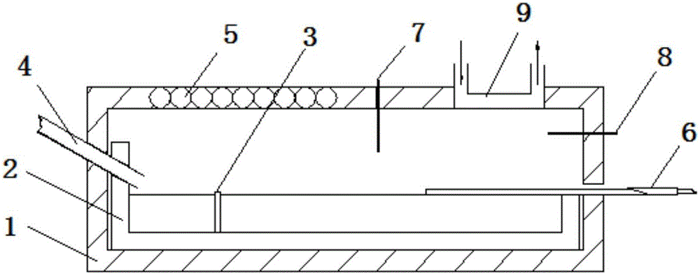
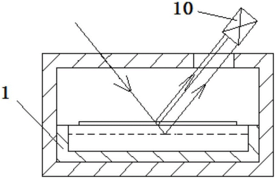
[0026] like figure 1 figure 2 As shown, a silicon wafer pulling device includes a heating furnace 1 and a control system. The heating furnace 1 is provided with a tong pot 2, and the tong pot 2 is provided with a partition 3. The existence of the partition 3 can prevent the , the melt fluctuation caused by the silicon material entering the melt; the partition 3 divides the inner cavity of the clamp pot 2 into a melting zone and a main zone, and a flow gap is opened on the partition 3 to connect the melting zone and the main zone, and the melting A heater 5 is fixedly arranged above the zone, and the left side of the heating furnace 1 is provided with a feeding pipe 4 for inser...


PUM


Abstract

The invention relates to a silicon wafer lifting device. The silicon wafer lifting device comprises a heating furnace and a control system, wherein a crucible is arranged in the heating furnace; a heater is fixedly arranged above a melting region; the heating furnace is provided with a feeding tube and an air inlet nozzle; a heat exchanger is fixedly arranged above a main region; a seed crystal bar is connected with a lifting mechanism arranged outside a cabin door; and the heating furnace is further provided with a first pyrometer and a second pyrometer. The control method comprises the following steps: a, adding a silicon material in the melting region of the crucible, and heating and melting the silicon material in the melting region; and b, after seed crystals enter a cavity, enabling the seed crystals to be in contact with melt, maintaining for 3-5 minutes, then starting the heat exchanger, enabling a motor to rotate reversely, enabling the seed crystal bars to move outwards, and enabling the lifting mechanism to move upwards to cut off silicon wafers after the lifting mechanism triggers a limiting switch. The silicon wafers obtained by the method cannot be polluted by the crucible during crystallization, therefore, the content of impurities of the silicon wafers is small, and material loss is expectedly reduced by 50%.

Description

technical field [0001] The invention relates to a silicon wafer pulling device and a control method thereof. Background technique [0002] Silicon is a non-metal with an atomic number of 14 and a relative atomic mass of 28.0855g / mol. It is widely used in the field of semiconductors and photovoltaics. In the existing mature technology, the Czochralski method (CZ method) and zone melting method (HZ method) are usually used to produce single crystal silicon. Monocrystalline silicon is mostly used in the semiconductor field, and both monocrystalline silicon and polycrystalline silicon are used in the photovoltaic industry. [0003] In the traditional vertical pulling method to grow monocrystalline silicon, due to the need to obtain ultra-thin silicon wafers, a large amount of post-processing (wire cutting, grinding and polishing, etc.) is required, and a large amount of raw materials are wasted in the post-processing process, resulting in The production cost is greatly increas...

Claims


Application Information

Patent Timeline
IPC IPC(8): C30B29/06C30B15/00C30B15/26
CPCC30B15/00C30B15/26C30B29/06
Inventor 丁建宁许嘉伟袁宁一张新伟
Owner CHANGZHOU UNIV
Learn More