Supercharge Your Innovation With Domain-Expert AI Agents!

UV adhesiveness control technique during in-situ shaping micro-lens manufacturing process

An in-situ forming and manufacturing process technology, applied in the fields of lenses, optics, instruments, etc., can solve problems such as high risk, complicated process, and inability to change, and achieve the effects of saving manufacturing costs, simplifying manufacturing processes, and simplifying manufacturing equipment

Inactive Publication Date: 2017-05-17
BEIJING UNIV OF TECH
View PDF5 Cites 4 Cited by
  • Summary
  • Abstract
  • Description
  • Claims
  • Application Information

AI Technical Summary

Problems solved by technology

In the actual production process, it is found that the high-voltage control process device is complicated, which leads to high manufacturing cost of the micro-lens, and the operation is very dangerous. Moreover, the direction of action of this method on the tension of the glue droplet is fixed along the direction of the electric field, and the opposite shape is complex. The aspheric surface control effect is very poor; the second process is complex, due to the agglomeration of nano-materials, the relationship between the concentration of nanoparticles and the control of surface shape change is difficult to grasp, and the doping has been completed before the micro-lens is manufactured. The doping concentration can no longer be adjusted, so that the finished microlens often cannot achieve any target surface shape; and the process of changing the roughness of the substrate is by polishing the surface of the substrate. Although the operation is relatively simple, it is also before the manufacturing process. It has been completed and cannot be changed during the manufacturing process, which greatly hinders the actual selectivity of the surface shape

Method used


Image

  • UV adhesiveness control technique during in-situ shaping micro-lens manufacturing process
  • UV adhesiveness control technique during in-situ shaping micro-lens manufacturing process
  • UV adhesiveness control technique during in-situ shaping micro-lens manufacturing process

Examples


Embodiment Construction

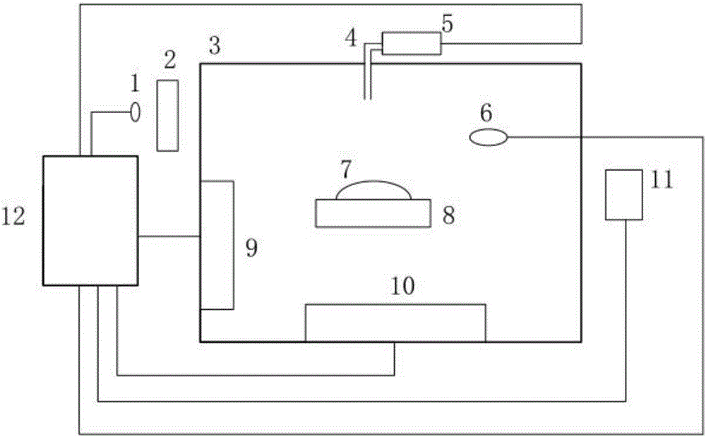
[0029] combine figure 2 To illustrate a specific embodiment of the present invention, the background light source 1 adopts a four-pin ceiling-mounted H-shaped lamp tube, the material of the heat insulation material chamber 3 adopts JGS2 ultraviolet optical quartz glass, the precision syringe pump 5 adopts a V6 precision syringe pump, and the ultraviolet light source 6 Using a laser light source, the energy density is limited to 5J / cm 2 within. Through the control circuit of the upper computer 12, the positive current is applied to the semiconductor refrigeration chip a9 and the semiconductor refrigeration chip b10, so that the semiconductor refrigeration chip starts to cool, and when the temperature in the cavity is close to 5°C, the ultraviolet optical glue in the precision syringe pump 5 is released through the glue droplet The catheter 4 is released onto the target substrate 8 with a volume of about 10 μl. At this time, the change in the shape of the glue droplet is detec...


PUM


Abstract

The invention discloses the UV adhesiveness control technique during an in-situ shaping micro-lens manufacturing process and belongs to the field of biology, analytical chemistry and medical detection. By rising or reducing temperature, the adhesiveness of ultraviolet optical glue is increased or reduced, so the flowing performance of glue drops is controlled and at this moment, the radius of curvature of a non-spherical surface of a glue drop is controlled. By radiating the glue drops by use of ultraviolet light beams timely, manufacturing of in-situ shaping micro-lens with a specific face shape is finished. The optical glue drop tension coefficient is changed by changing the temperature, so the adhesiveness of the glue drops is changed, thereby changing the rules of shape change of non-spherical tops of the optical glue drops. In change processes of all kinds of non-spherical glue drops, strong laser is used for carrying out procuring on surfaces of the glue drops when it is captured that the shapes of the tops of the non-spherical tops of the optical glue drops are matched with the design shape and then the heights of the non-spherical tops are changed by changing the temperature, so the focal points are allowed to fall on required working faces. Thus, micro-lens manufacturing cost is reduced, and manufacturing technique is simplified.

Description

technical field [0001] The invention proposes a surface shape control process in the micro-manufacturing process of in-situ forming optical micro-lenses, which is mainly used to manufacture micro-lenses on the light filters of the light excitation unit and the light detection unit of the biochip detection system, in terms of structure miniaturization, function On the basis of integration, the aim of improving the focusing efficiency of the fluorescence excited by the detected object and improving the detection sensitivity of the biochip belongs to the fields of biology, analytical chemistry and medical detection. Background technique [0002] Microfluidic chip and detection technology is a high-tech that has developed very rapidly in the field of life sciences in recent years. It can realize all biological analysis processes such as sampling, dilution, injection, reaction, separation and detection on the basis of miniaturization. And other functions are integrated into a chi...

Claims


Application Information

Patent Timeline
IPC IPC(8): G02B3/00
CPCG02B3/00
Inventor 郭威吴坚陈昭文陈涛
Owner BEIJING UNIV OF TECH
Features
  • R&D
  • Intellectual Property
  • Life Sciences
  • Materials
  • Tech Scout
  • Unparalleled Data Quality
  • Higher Quality Content
  • 60% Fewer Hallucinations
Learn More