Network monitoring method and device based on polling matching

A network monitoring and self-matching technology, applied in electromagnetic wave transmission systems, electrical components, transmission systems, etc., can solve problems affecting the judgment of optical fiber link faults, and achieve the effects of simple structure, reduced use cost, and low system cost

Active Publication Date: 2017-05-17
SOUTHEAST UNIV
View PDF7 Cites 5 Cited by
  • Summary
  • Abstract
  • Description
  • Claims
  • Application Information

AI Technical Summary

Problems solved by technology

The line width of the tunable light source is an important parameter of coherent noise. The narrower the line width, the greater the coherent noise, and the greater the amplitude jitter of the attenuation curve measured by the tunable 0TDR, which affects the judgment of fiber link failures.

Method used


Image

  • Network monitoring method and device based on polling matching
  • Network monitoring method and device based on polling matching
  • Network monitoring method and device based on polling matching

Examples


Embodiment 1

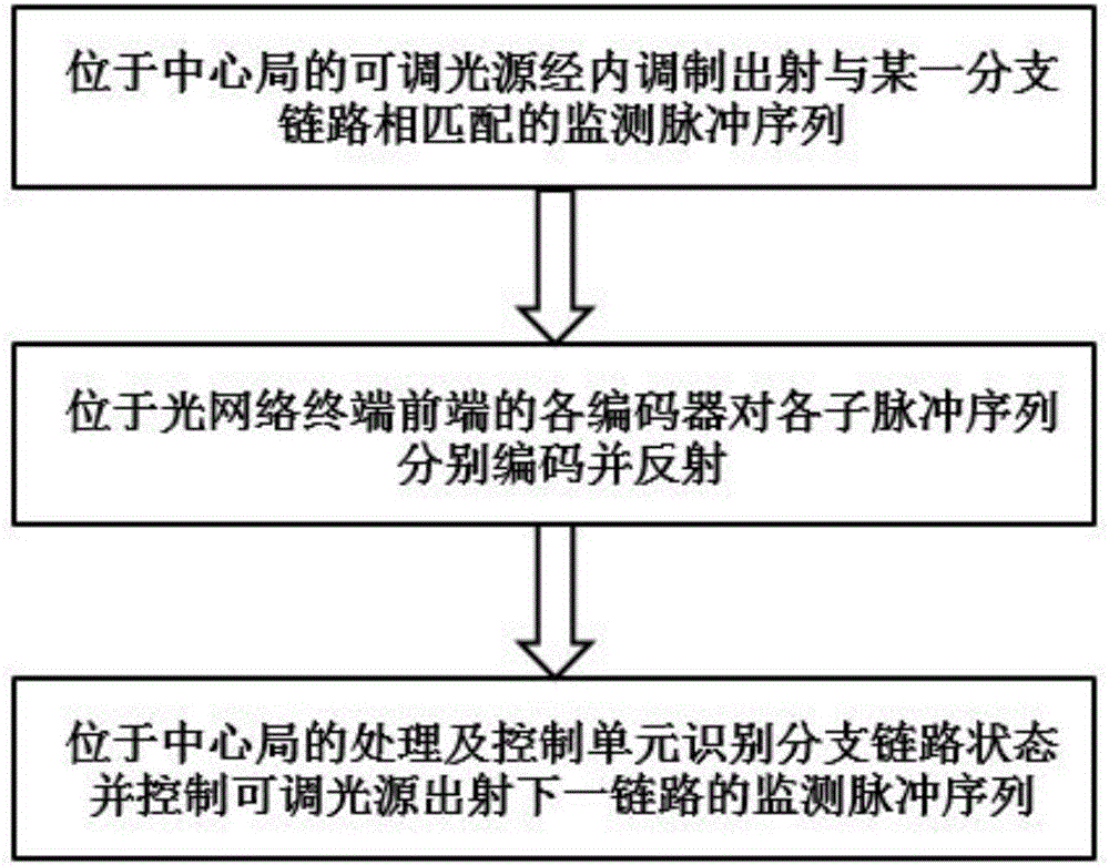
[0030] A network monitoring method based on polling self-matching, according to the instructions sent by the processing and control unit 6, the network monitoring of the links to be monitored is completed one by one; the method for performing network monitoring on each link to be monitored is as follows:

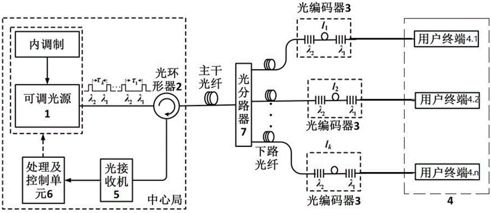
[0031]According to the instructions issued by the processing and control unit 6, the adjustable light source 1 is modulated in the link to be monitored and emits a monitoring pulse sequence corresponding to the link to be monitored, and the monitoring pulse sequence is transmitted from the a port of the optical circulator 2 Incident, the b port of the circulator 2 reaches the optical splitter through the trunk fiber; the optical splitter divides the monitoring pulse sequence into k sub-pulse sequences, and the optical splitter is connected to each port of the optical splitter. They are respectively dropped to each optical encoder and each user terminal, where k is the total n...

Embodiment 2

[0038] A network monitoring device based on polling self-matching, comprising: an adjustable light source 1, an optical circulator 2, an optical splitter 7, an optical receiver 5 and a processing and control unit 6, each output port of the optical receiver 5 A link including an optical encoder 3 and a user terminal 4 is respectively connected to the optical encoder, the optical encoder includes a first fiber Bragg grating and a second fiber Bragg grating fiber delay line, and the output end of the first fiber Bragg grating is extended through an optical fiber. The time line is connected to the input end of the second fiber Bragg grating, and the input end of the second fiber Bragg grating is connected to the user terminal 4;

[0039] The adjustable light source 1 is used to receive instructions from the processing and control unit 6, modulate and emit a monitoring pulse sequence corresponding to the link to be monitored for the link to be monitored; the monitoring pulse sequenc...


PUM


Abstract

The invention discloses a network monitoring method and device based on polling matching; modulation is carried out in links to be monitored by an adjustable light source, while a monitoring pulse sequence corresponding to the links to be monitored emerges, and states of the links to be monitored are recognized one by one through a command transmitted by a receiving processing and control unit; the network monitoring method enables branch fiber links in a passive optical network to be effectively monitored; the states of the branch fiber links are judged respectively at a receiving end through unique signal characteristics generated by matching of the monitoring pulse sequence and a terminal encoder; in addition, the network monitoring device has simple structure and enables system and user costs to be effectively reduced.

Description

technical field [0001] The invention belongs to the technical field of optical fiber communication, and relates to a network monitoring method and device based on polling self-matching. Background technique [0002] In the process of domestic operators' "light into copper back" construction in full swing, the passive optical network system began to be commercialized on a large scale. For this system, effective operation, maintenance and management is a problem that cannot be ignored but needs to be solved urgently. It is particularly important to quickly find, locate and deal with optical layer faults in passive optical networks. At the same time, for various technologies of optical link monitoring, factors such as cost, implementation difficulty and effectiveness largely limit the practical application of specific technologies. Therefore, an easy-to-implement and low-cost monitoring technology will play an important role in actual deployment. [0003] As we all know, the ...

Claims


Application Information

Patent Timeline
Patent Type & Authority Applications(China)
IPC IPC(8): H04B10/071
CPCH04B10/071
Inventor 孙小菡张旋陈斯戈志群朱敏
Owner SOUTHEAST UNIV
Why Eureka
Try Eureka