General frequency matching longitudinal-torsional compound ultrasonic vibration milling and drilling device

A frequency matching and composite ultrasonic technology, applied in the field of precision and ultra-precision finishing, can solve the problems of increasing processing cost, small torsional vibration component, reducing processing efficiency, etc., to ensure connection reliability, increase amplification factor, and improve general-purpose sexual effect

Active Publication Date: 2017-05-24
CONPROFE TECH GRP CO LTD +1
View PDF8 Cites 38 Cited by
  • Summary
  • Abstract
  • Description
  • Claims
  • Application Information

AI Technical Summary

Problems solved by technology

[0003] At present, there are mainly two methods to realize longitudinal-torsional composite ultrasonic vibration. One is to polarize the piezoelectric ceramic along the tangential direction, but it is technically difficult to achieve. The usual method is to first cut the piezoelectric ceramic sheet into several fan-shaped sheets, Separately tangentially polarize each sector-shaped piezoelectric ceramic sheet, and then bond each sector-shaped piezoelectric ceramic sheet together. This method is complex in process, high in scrap rate, and prone to incomplete polarization of the ceramic sheet, electrical breakdown, etc. The problem is that it is difficult to manufacture an ideal transducer; the second is to carry out a special design on the structure of the horn, such as the chute type, etc., but it is found in practical applications that the torsional vibration component of this method is small, and the longitudinal vibration component cannot be fully utilized. The advantages of torsional composite ultrasonic vibration, the processing efficiency is low, so that the processing eff

Method used


Image

  • General frequency matching longitudinal-torsional compound ultrasonic vibration milling and drilling device
  • General frequency matching longitudinal-torsional compound ultrasonic vibration milling and drilling device
  • General frequency matching longitudinal-torsional compound ultrasonic vibration milling and drilling device

Examples


Embodiment Construction

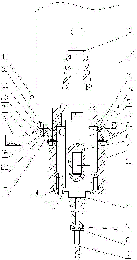
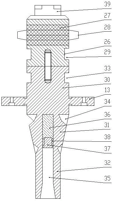
[0022] Such as figure 1 with figure 2 As shown, a general-purpose frequency-matched longitudinal-torsional composite ultrasonic vibration milling and drilling device of the present invention includes a machine tool spindle 1, a spindle housing 2, an ultrasonic power supply 3, an ultrasonic wireless power transmission system, a mounting cylinder 4, and a sleeve 5. Longitudinal ultrasonic vibration transducer 6. Hollow spiral grooved horn 7. Spring collet 8. Compression nut 9 and cutter 10 (end milling cutter).

[0023] The power output end of the machine tool spindle 1 is arranged vertically downward, the machine tool spindle 1, the installation cylinder 4, the sleeve 5, the hollow spiral groove type horn 7 and the cutter 10 have the same rotation center line, the lower end of the machine tool spindle 1 and the installation The upper end of the cylinder 4 is connected to the axial transmission, the lower part of the installation cylinder 4 protrudes from the main shaft housin...


PUM

PropertyMeasurementUnit
Diameteraaaaaaaaaa
Lengthaaaaaaaaaa

Abstract

The invention discloses a general frequency matching longitudinal-torsional compound ultrasonic vibration milling and drilling device. The device comprises a machine tool main shaft, a main shaft shell, an ultrasonic power supply, an ultrasonic wireless electric energy transmission system, a mounting cylinder, a sleeve, a longitudinal ultrasonic vibration transducer, a hollow spiral groove amplitude change rod, an elastic chuck, a pressing nut and a cutter. The device adjusts the positions of a rubber plug and a sealing ring to change the volume of a fluid in a cylindrical groove or to replace the type of the fluid so as to change the mass of a longitudinal-torsional compound ultrasonic vibrator to compensate the frequency loss or increment in clamping of different cutter rods; and when the different cutter rods are clamped, the consistency of the resonant frequency, the vibration mode and the vibration shape of an ultrasonic device is realized, and the generality of the device is greatly improved. The longitudinal vibration and torsional vibration effects are both enhanced to a certain extent; the working efficiency is greatly improved; and the advantages of longitudinal-torsional compound vibration are preferably exerted.

Description

technical field [0001] The invention belongs to the technical field of precision and ultra-precision finishing, and in particular relates to a universal frequency-matched longitudinal-torsional composite ultrasonic vibration milling and drilling device. Background technique [0002] Compared with ordinary machining, ultrasonic vibration machining has the advantages of reducing cutting force, reducing tool wear, improving workpiece surface machining accuracy and improving machining efficiency. Traditional ultrasonic machining is mostly a single vibration mode. However, with the development of ultrasonic machining technology and continuous improvement of equipment, composite vibration modes such as longitudinal-torsion, longitudinal-bend and torsion-bend have also received extensive attention. Studies have shown that milling under the ultrasonic longitudinal-torsional composite vibration mode can further reduce the cutting force during the cutting process, improve the efficien...

Claims


Application Information

Patent Timeline
IPC IPC(8): B23B37/00
CPCB23B37/00
Inventor 赵波殷森李瑜王亮亮赵重阳王晓博
Owner CONPROFE TECH GRP CO LTD
Why Eureka
Try Eureka