Resolution-adjustable wavelength selection switch based on phase grating array and control method

A wavelength selective switch and resolution technology, applied in the field of optical communication and optical signal processing, can solve the problems of unadjustable working wavelength range and resolution, insufficient spectral resolution, etc. Easy to assemble and adjust the optical path

Pending Publication Date: 2017-05-31
MINZU UNIVERSITY OF CHINA
View PDF5 Cites 19 Cited by
  • Summary
  • Abstract
  • Description
  • Claims
  • Application Information

AI Technical Summary

Problems solved by technology

[0004] In view of the two technical problems of insufficient spectral resolution and unadjustable working wavelength range and resolution of the current wavelength selective switch, the present invention proposes a wavelength resolution controllable based on a specially designed transmissive phase diffraction grating array. and wavelength selective switch for adjustment of the operating wavelength range

Method used


Image

  • Resolution-adjustable wavelength selection switch based on phase grating array and control method
  • Resolution-adjustable wavelength selection switch based on phase grating array and control method
  • Resolution-adjustable wavelength selection switch based on phase grating array and control method

Examples


Embodiment 1

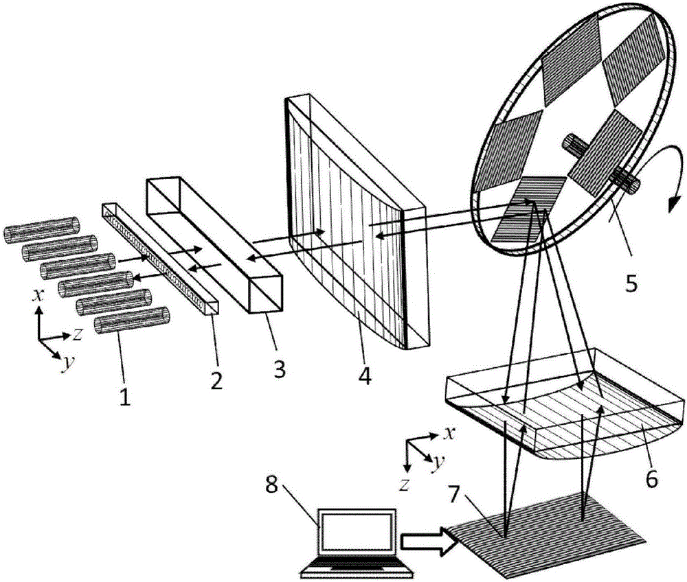
[0032] Such as figure 2 As shown, in this embodiment, the transmission type phase diffraction grating array 5 adopts a rotating type transmission type phase diffraction grating array, which is connected to the grating angle encoder, and a plurality of transmission type phase diffraction gratings with different periods are arranged on the circumference, and the grating Driven by the rotation of the angle encoder, it can rotate around the center of the circle, so as to realize the program-controlled switching of the transmissive phase diffraction gratings with different periods in the optical path.

[0033] The transmission phase diffraction grating adopts the zero-order suppression transmission phase grating etched on the silicon substrate or the quartz substrate; the period of the transmission phase diffraction grating is in the range of 100-1200nm.

Embodiment 2

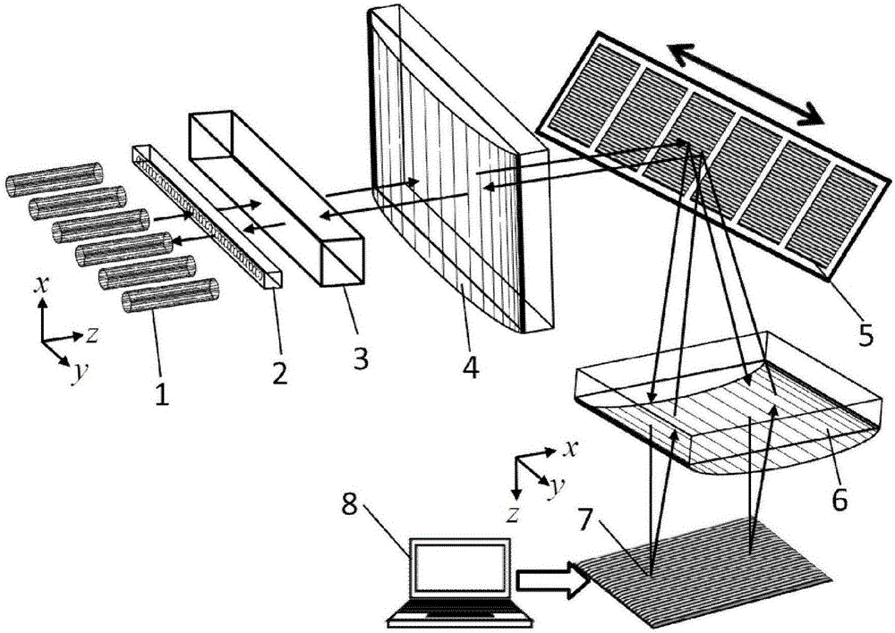
[0035] Such as image 3 As shown, in this embodiment, the transmission type phase diffraction grating array 5 adopts a translational one-dimensional transmission type phase diffraction grating array, which is connected to the grating angle encoder, and a plurality of transmission type phase diffraction gratings with different periods are arranged along a straight line, and in Driven by the grating displacement encoder, it translates along a straight line to realize the program-controlled switching of different periods of the transmissive phase diffraction grating in the optical path.

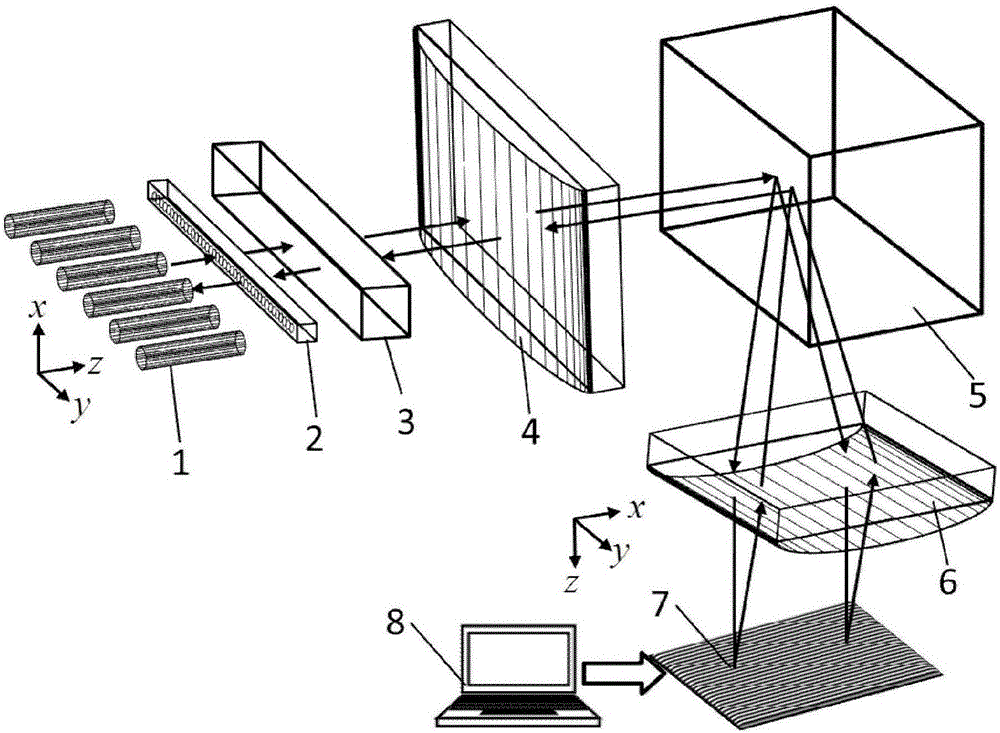
[0036] Figure 4 It is the optical schematic diagram of the wavelength selective switch with high port number based on the optical beam expander of the present invention. The one-dimensional optical fiber array 1 and the liquid crystal spatial light modulator 7 are respectively located at the focal points on both sides of the double-bonded optical Fourier transform lens 4, and the transmissive ...


PUM


Abstract

The invention discloses a resolution-adjustable wavelength selection switch based on a phase grating array and a control method. The resolution-adjustable wavelength selection switch comprises a one-dimensional single mode fiber array, a microlens array, a polarization adjusting prism, a double-glued optical Fourier transformation lens, a transmissive phase diffraction grating array, a cylindrical mirror, a liquid crystal spatial light modulator and a graph loading control system. The transmissive phase diffraction grating array is adopted, difference in chromatic dispersivity of transmissive phase diffraction gratings different in period is utilized, and wavelength range of parallel beams finally imaged on the liquid crystal spatial light modulator and wavelength control accuracy determined by a single pixel unit can be changed by switching the transmissive phase diffraction gratings having different periods, so that switching and adjusting of working wavelength range and wavelength resolution of the wavelength selection switch are realized, and the wavelength selection switch can be used for processing large-bandwidth high-speed signals in backbone networks.

Description

technical field [0001] The invention relates to the field of optical communication and optical signal processing, in particular to a wavelength selective switch with adjustable resolution and a control method thereof based on a transmissive phase grating array. Background technique [0002] Since the beginning of the 21st century, with the continuous and huge growth of optical network traffic at a rate of 100 times in 10 years, the existing electrical layer switching technology has many advantages in terms of the number and volume of equipment, information exchange capacity, construction and operation costs, and energy consumption. The "ceiling effect" has become increasingly prominent. Building a next-generation low-energy and high-spectrum-efficiency intelligent all-optical communication network based on all-optical switching, multi-dimensional multiplexing, high-spectrum utilization super-channel transmission and switching technology, and software dynamic adjustment of ne...

Claims


Application Information

Patent Timeline
Patent Type & Authority Applications(China)
IPC IPC(8): G02B6/293G02F1/13G02B6/32G02B6/27
CPCG02F1/1313G02B6/27G02B6/29311G02B6/32
Inventor 陈根祥高云舒陈笑宋菲君王义全张策官家祥张颖
Owner MINZU UNIVERSITY OF CHINA
Why Eureka
Try Eureka