Anti-condensation coating, radiation terminal with anti-condensation coating on surface, radiator and air-conditioning system

An anti-condensation and coating technology, which is used in air-conditioning systems, conductive coatings, and prevention of condensed water, etc., can solve the problems of poor heating experience, complex structure of refrigeration systems, and easy condensation on the surface of cold and hot radiant panels, and achieve improved stability. performance and longevity, simplified subsequent operation process, good anti-condensation effect

Active Publication Date: 2017-06-13
中安瑞材(北京)科技有限公司
View PDF9 Cites 6 Cited by
  • Summary
  • Abstract
  • Description
  • Claims
  • Application Information

AI Technical Summary

Problems solved by technology

Although during cooling in summer, the temperature of the cold and warm water pipes is higher than that of the refrigerant pipes, the risk of condensation is smaller than that of the radiant panels with refrigerant inside, but the surface of the cold and hot radiant panels is still prone to condensation in high humidity weather. dew
[0008] Aiming at the problem that the outdoor unit is prone to frost in winter, the existing technology usually adopts two solutions. One way is to switch the four-way reversing valve so that the indoor unit becomes an evaporator and the outdoor unit becomes a condenser. The other way is to set Bypass pipe, when defrosting is required, part of the high-temperature refrigerant discharged from the compressor flows through the bypass pipe through the radiator of the outdoor unit to achieve the purpose of defrosting, but the former will lead to poor heating experience, while the latter will lead to cooling The system structure is complex and prone to failure
[0009] For the radiant panels of radiant air conditioners, the prior art discloses that the surface of some radiant panels can be coated with an anti-condensation coating, but experiments have shown that the dew point temperature cannot be effectively reduced, and there is still a large risk of condensation and mildew in the room
[0010] In summary, there is no method in the prior art that can fundamentally solve the problem of easy condensation and frost on the surface of the radiator or radiation surface in a high-humidity environment.

Method used


Image

  • Anti-condensation coating, radiation terminal with anti-condensation coating on surface, radiator and air-conditioning system

Examples


preparation example Construction

[0043] The preparation method of the anti-condensation coating comprises the steps:

[0044] (1) Preparation of graphene-coated particle mixture:

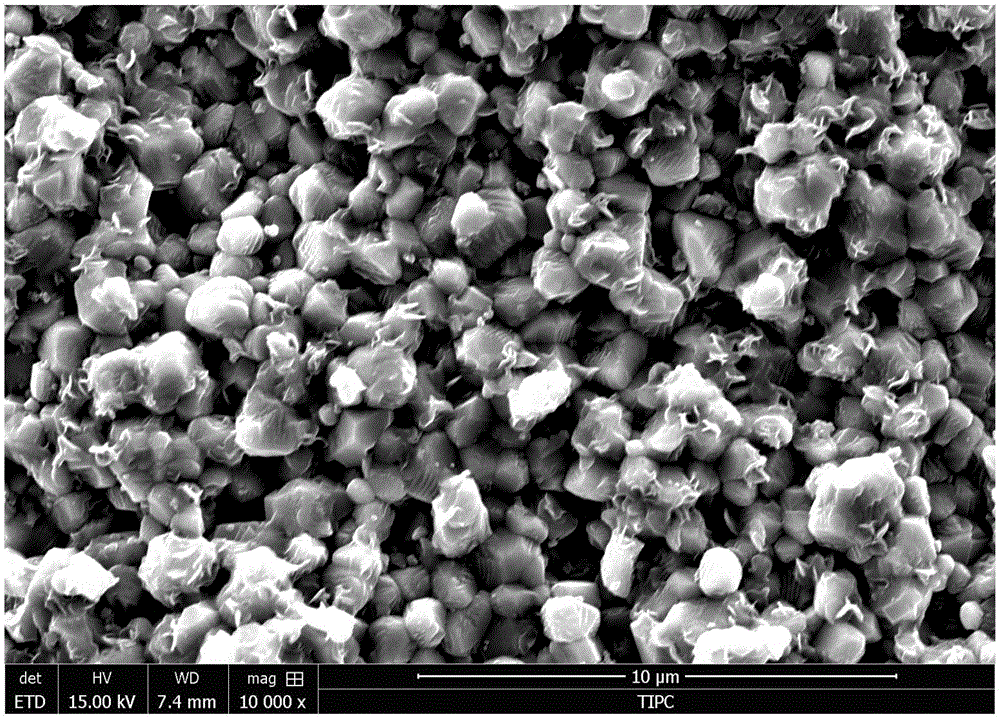
[0045] 85-99 wt. % of a particle mixture with a particle size of 0.2-5 μm (in which the volume ratio of inorganic particles to organic particles is 1:2), 0.5-10 wt. % of graphene and 0.5-5 wt. % of dispersant are added to Mixing thoroughly in absolute ethanol by wet ball milling for 2-12 hours to coat the surface of the particles with flake graphene; then fully drying and passing through a 500-mesh sieve; obtaining a graphene-coated particle mixture; the graphene-coated A typical SEM photo of a particle mixture such as figure 1 As shown, it can be observed that a layer of thin-film graphene is coated on the surface of the particle;

[0046] (2) Preparation of anti-condensation coating:

[0047] Under certain temperature and / or atmosphere protection conditions, 40-79% of superhydrophobic raw material, 1-10% of graphene and 20-50%...

Embodiment 1

[0049] (1) 90wt.% of PTFE powder with an average particle size of 500nm and TiO 2 The particle mixture (volume ratio of 2:1) was added to anhydrous ethanol solvent with 5wt.% graphene and 5wt.% PEG-400, followed by ball milling for 4 hours; the ball-milled slurry was placed in an oven at 60 °C to dry 8 hours, followed by grinding and sifting through a 500 mesh screen; a graphene-coated Teflon / titanium dioxide particle mixture was obtained.

[0050] (2) 40wt.% of the graphene-coated polytetrafluoroethylene / titanium dioxide particle mixture, 10% of graphene and 50wt.% of perfluorooctadecyltrichlorosilane were dissolved in n-hexane and thoroughly mixed; Condensation paint.

[0051] After the coating is sprayed and dried, the contact angle of the coating to water can reach 150°, and it can heat up to 38°C when connected to a voltage of 24V.

Embodiment 2

[0053] (1) 95wt.% of polyvinylidene fluoride / Al having an average particle size of 1 μm 2 O 3 The particle mixture (volume ratio of 2:1) was added to anhydrous ethanol solvent with 3wt.% graphene and 2wt.% PEG-400, followed by ball milling for 8 hours; the slurry after ball milling was placed in a 60°C oven to dry 8 hours, followed by grinding and sieving through a 500 mesh screen; a graphene-coated polyvinylidene fluoride / alumina particle mixture was obtained.

[0054] (2) 30wt.% of the graphene-coated polyvinylidene fluoride / alumina particle mixture, 5% of graphene and 65% of perfluoropolymethacrylate were dissolved in trifluorotrichloroethane and thoroughly mixed ; Obtain anti-condensation paint.

[0055] After the coating is sprayed and dried, the contact angle of the coating to water can reach 157°, and it can heat up to 25°C when connected to a 24V voltage.


PUM

PropertyMeasurementUnit
particle diameteraaaaaaaaaa

Abstract

The invention provides an anti-condensation coating, a radiation terminal with the anti-condensation coating on surface, a radiator or an air-conditioning system. The anti-condensation coating comprises a functional material and an organic solvent, wherein the functional material comprises the following materials by weight percent: 40-79wt% of super-hydrophobic raw material, 1-10wt% of graphene and 20-50wt% of mixture of graphene coated inorganic particle and fluorine-containing organic particle. The mixture of graphene coated inorganic particle and fluorine-containing organic particle comprises a particle mixture in the grain size of 0.2-5 mu m and the graphene coating the particle mixture. The radiation terminal with the anti-condensation coating, the radiator and/or the air-conditioning system provided by the invention can be used for solving the problem of the prior art that air conditioning and heating are not matched and used with each other, so that the indoor heating radiator and the radiation terminal are difficult to dew in summer and the outdoor heat radiator is difficult to dew.

Description

technical field [0001] The invention relates to the field of coatings, in particular to an anti-condensation coating, a radiation terminal, a radiator and an air-conditioning system having the anti-condensation coating on the surface. Background technique [0002] In the interior of buildings in northern my country, district heating or central heating is generally used in winter, generally obtaining heat through radiators, while in summer, central air conditioning or distributed air conditioning is used to provide cooling to the room through heat exchange between refrigerant and air. The use of heating and air conditioning is usually independent of each other. Only when the indoor heat load is insufficient, the air conditioning will provide a part of auxiliary heat, and the comprehensive utilization rate of heating equipment and cooling equipment is low. [0003] When the air conditioner is used as a heat pump in winter, the outdoor unit is easily frosted in a humid and cold ...

Claims


Application Information

Patent Timeline
Patent Type & Authority Applications(China)
IPC IPC(8): C09D183/08C09D133/16C09D5/24C09D7/12F24F1/14F24F13/22
CPCC09D4/06C09D5/24C09D7/61C09D7/62C09D133/16F24F1/14F24F13/22F24F2013/221C08L27/18C08K9/10C08K2003/2227C08K3/04
Inventor 宋波向长松袁征
Owner 中安瑞材(北京)科技有限公司
Why Eureka
Try Eureka