Technological method and system for driving main exhaust fan by using vertical cold kiln to recover waste heat of sintered ore

A main exhaust fan, process system technology, applied in the direction of machine/engine, process efficiency improvement, mechanical equipment, etc., can solve the problems affecting the operation of discharge conveying equipment, heat recovery rate and calorific value, high equipment maintenance costs, and material distribution. Non-uniformity and other problems, to achieve the effect of improving the production environment, novel structure, energy saving and effect creation

Pending Publication Date: 2017-06-30
鞍钢集团工程技术有限公司 +1
View PDF20 Cites 12 Cited by
  • Summary
  • Abstract
  • Description
  • Claims
  • Application Information

AI Technical Summary

Problems solved by technology

[0008] In summary, existing vertical cooling kilns generally have problems such as poor sealing and uneven distribution of materials, resulting in poor site environment, high discharge temperature, and low temperature o

Method used


Image

  • Technological method and system for driving main exhaust fan by using vertical cold kiln to recover waste heat of sintered ore
  • Technological method and system for driving main exhaust fan by using vertical cold kiln to recover waste heat of sintered ore
  • Technological method and system for driving main exhaust fan by using vertical cold kiln to recover waste heat of sintered ore

Examples


Embodiment Construction

[0035] The specific embodiment of the present invention will be further described below in conjunction with accompanying drawing:

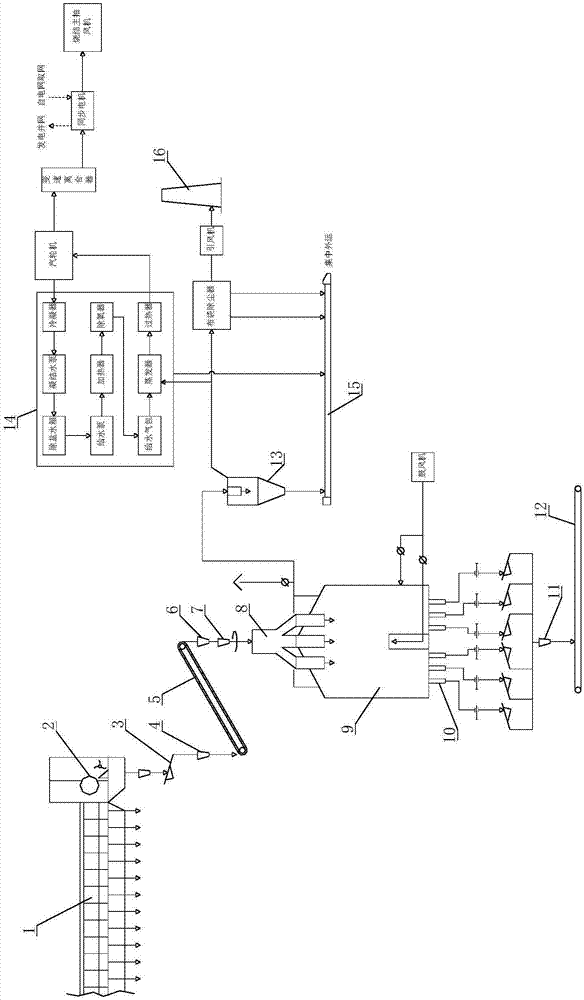
[0036] like figure 1 Shown, the technical method of the present invention reclaims sinter waste heat to drive main exhaust fan with vertical cold kiln, comprises the steps:

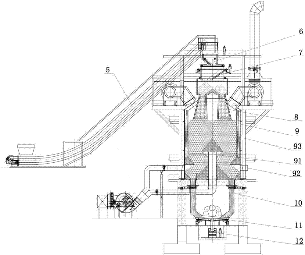
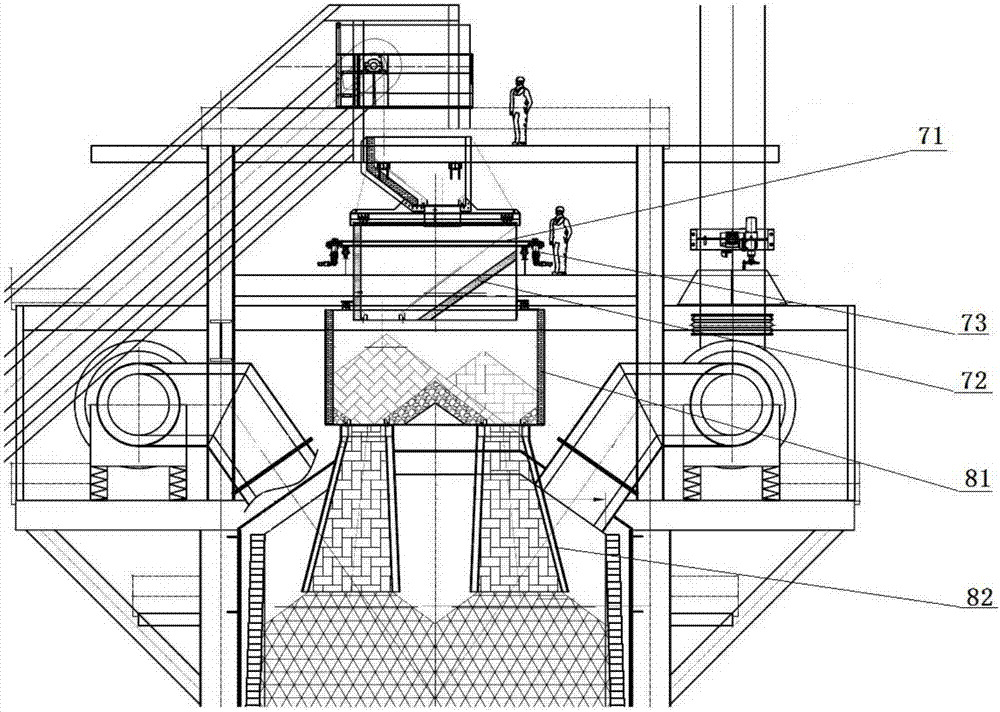
[0037] 1) The hot sintered ore above 700°C produced by sintering machine 1 is crushed by single roll crusher 2 and then falls into chute 3, fed to chain bucket conveyor 5 by electric vibrating feeder 1, and then lifted into vertical cooling kiln 9; The upper part of the vertical cooling kiln 9 is provided with a rotary distributor 7 and a distributor 8, and the distributor 8 is composed of a plurality of discharge chutes 82 uniformly distributed along the circumference of the vertical cooling kiln 9; the sintered ore is discharged from the head of the chain bucket conveyor 5 The material enters the rotary distributor 7 through the receiving chute 6, and the rotary distributo...


PUM


Abstract

The invention relates to a technological method and system for driving a main exhaust fan by using a vertical cold kiln to recover waste heat of sintered ore. The hot sintered ore is subjected to heat exchange with cold air in the vertical cold kiln, waste gas is conveyed to a waste heat boiler after being subjected to dedusting, and generated superheated steam is conveyed to a steam turbine; and the steam turbine directly drives the sintering main exhaust fan to operate through a variable-speed clutch and a synchronous motor. By the adoption of the vertical cold kiln of a novel structure, the recovery rate of the waste heat of the sintered ore can be increased to the maximum extent; complementation between electricity generation of the steam turbine and electric energy of a power grid is achieved through the synchronous motor, and normal operation of the sintering main exhaust fan is guaranteed; and the complete sintering plant energy utilization technological system is composed of the vertical cold kiln, the waste heat boiler, the steam turbine and the sintering main exhaust fan, the steam turbine directly provides power for the main exhaust fan, electricity obtained from the power grid is reduced, secondary efficiency loss occurring due to the fact that in the conventional technique, when electricity is generated by the steam turbine and incorporated into the power grid and the sintering main exhaust fan obtains electricity from the power grid, mechanical energy is converted into electric energy and the electric energy is reconverted into the mechanical energy can be avoided, and great significance is brought to energy saving and value creating.

Description

technical field [0001] The invention relates to the technical field of sinter waste heat recovery and utilization, in particular to a process method and system for driving a main exhaust fan by recovering sinter waste heat from a vertical cooling kiln. Background technique [0002] The main exhaust fan is the largest energy-consuming equipment in the sintering plant, and its power consumption is about 30% of the total power consumption of the whole plant; 2 Take the sintering machine (95% operating rate) as an example. The power of the main exhaust fan is 8000kW, and the annual power consumption is about 56630MWh. Calculated at 0.547 yuan / kWh, the annual electricity fee is 30.98 million yuan. [0003] The temperature of the sintered ore is about 700-750°C. The blast furnace is supplied with cold ore. Due to the structural characteristics of the equipment, the annular cooler and the belt cooler can only recover about 30% of the heat of the exhaust gas; the vertical cooling ki...

Claims


Application Information

Patent Timeline
IPC IPC(8): F27D15/02F27D17/00F27D3/00F01D15/10F04D25/08
CPCF01D15/10F04D25/08F27D3/00F27D15/0286F27D17/004F27D2017/006F27M2003/04Y02P10/25
Inventor 冯占立于丽娟李霞皮特·普奇兹李益民宫作岩卡斯特内·马克余盈昌夏铁玉李辉考普勒梅·大力费雷戈·爱得赵水生郭伟
Owner 鞍钢集团工程技术有限公司
Why Eureka
Try Eureka