Manufacturing method of infrared reflecting device

An infrared reflection and device technology, applied in chemical instruments and methods, instruments, building components, etc., can solve the problems that the optical performance cannot be changed, and people cannot be satisfied.

Inactive Publication Date: 2017-08-01
SOUTH CHINA NORMAL UNIVERSITY +2
View PDF5 Cites 12 Cited by
  • Summary
  • Abstract
  • Description
  • Claims
  • Application Information

AI Technical Summary

Problems solved by technology

[0004] However, after the coated glass is formed, its optical

Method used


Image

  • Manufacturing method of infrared reflecting device
  • Manufacturing method of infrared reflecting device
  • Manufacturing method of infrared reflecting device

Examples


Embodiment 1

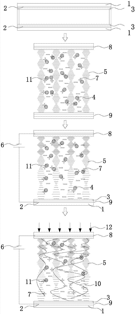
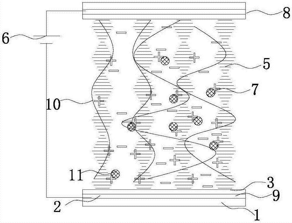
[0028] refer to figure 1 Prepare the infrared reflective device according to the following steps, firstly prepare the first conductive light-transmitting substrate 8 and the second conductive light-transmitting substrate 9, the first conductive light-transmitting substrate 8 and the second conductive light-transmitting substrate 9 are arranged oppositely, so The first conductive light-transmitting substrate 8 and the second conductive light-transmitting substrate 9 both include a substrate 1, and the opposite surfaces of the two substrates 1 are covered with a conductive layer 2; The alignment layer 3 is spin-coated on the opposite surface of the second conductive light-transmitting substrate 9, and rubbed in parallel orientation, that is, the alignment layer 3 is spin-coated on the conductive layer 2; the first conductive light-transmitting substrate 8 and the second The conductive light-transmitting substrate 9 is prepared into a liquid crystal cell; according to the mass ra...

Embodiment 2

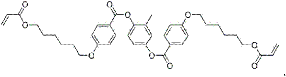
[0038] This example is basically the same as Example 1, except that the mass ratio of the negative liquid crystal: chiral dopant: photopolymerizable monomer: photoinitiator is 79.5:14.5:5:1, and the The liquid crystal monomer has an ester group capable of trapping cations. The liquid crystal monomer is RM257. The chiral dopant is R811. Described photoinitiator is Irgacure-369, and its structural formula is:

[0039]

[0040] The negative liquid crystal is HNG30400-200. Ultraviolet light irradiates the liquid crystal cell from one side of the first conductive light-transmitting substrate.

Embodiment 3

[0042] This example is basically the same as Example 1, except that the mass ratio of the negative liquid crystal: chiral dopant: photopolymerizable monomer: photoinitiator is 80.4:13.6:5:1, and the The chiral dopant has an ester group capable of trapping cations. The liquid crystal monomer is M04031. The chiral dopant is S1011. The photoinitiator is Irgacure-369. The negative liquid crystal is HNG708200-100.


PUM


Abstract

The invention discloses a manufacturing method of an infrared reflecting device. The manufacturing method of the infrared reflecting device comprises the following steps: making a first conductive light transmitting substrate and a second conductive light transmitting substrate at first, and enabling the two conductive light transmitting substrate to opposite to each other; manufacturing parallel orientation layers on the opposite surfaces of the two conductive light transmitting substrates; manufacturing a liquid crystal box by using the two conductive light transmitting substrates; mixing negative liquid crystal, a chiral dopant, liquid crystal monomers and a photoinitiator to obtain a liquid crystal mixture; injecting the liquid crystal mixture in the liquid crystal box; connecting the first conductive light transmitting substrate with a negative pole of a power supply assembly, connecting the second conductive light transmitting substrate with a positive pole of the power supply assembly, capturing impurity positive ions by using the liquid crystal monomers and/or the chiral dopant so that the liquid crystal monomers and/or the chiral dopant have positive charge, and enabling the liquid crystal monomers and/or the chiral dopant to continue moving towards the negative pole direction; and carrying out ultraviolet irradiation to polymerize the liquid crystal monomers so as to form a polymer network, and enabling the densities of the polymer network to be distributed in a gradient manner in the direction perpendicular to the conductive light transmitting substrate to obtain the infrared reflecting device with wide reflection bandwidth. By change of the direction of an electric field, infrared reflection waveband can be adjusted.

Description

technical field [0001] The invention relates to the technical fields of optics and liquid crystal devices, in particular to a preparation method of an infrared reflective device. Background technique [0002] People generally work indoors, so the comfort of the indoor environment has a great impact on people's enthusiasm for work. Indoor and other environments generally use cooling or heating devices to adjust the temperature to achieve comfort. [0003] In order to achieve the purpose of sunlight transmission and reflection, the glass is generally coated so that light of a certain wavelength in the light can be reflected or transmitted by the glass window. Coated glass is coated with one or more layers of metal, alloy or metal compound films on the surface of the glass to change the optical properties of the glass and achieve the purpose of reflecting or transmitting light of a certain wavelength. [0004] However, after the coated glass is formed, its optical properties ...

Claims


Application Information

Patent Timeline
IPC IPC(8): G02F1/137G02F1/1335
CPCG02F1/133553G02F1/13718G02F1/13712E06B3/6722G02F2203/11G02F2203/02G02F2202/022G02F1/133365G02F1/13476G02F2203/055C09K2019/0448C09K19/586C09K19/54E06B9/24E06B2009/2417G02F1/1316G02F1/1334G02F1/1337G02F1/1341G02F1/13345
Inventor 胡小文曾伟杰李楠周国富
Owner SOUTH CHINA NORMAL UNIVERSITY
Why Eureka
Try Eureka