Iron ore sintering system and method

A technology of iron ore and sintered ore, which is applied in the fields of steelmaking and environmental protection, can solve the problems of secondary pollution, large investment, and difficulty in industrialization and application, and achieve the improvement of waste heat recovery efficiency, energy utilization efficiency, and elimination of white smoke vision pollution effect

Inactive Publication Date: 2017-09-15
SHANGHAI JIAO TONG UNIV +1
View PDF6 Cites 1 Cited by
  • Summary
  • Abstract
  • Description
  • Claims
  • Application Information

AI Technical Summary

Problems solved by technology

The engineering investment of activated coke adsorption technology is huge, but the defect of MEROS flue gas purification technology is that there is secondary pollution, that is, it contains 2 The generated lignite or activated coke dust adsorbed with dioxin / furan should be discarded after repeated use
[0007] In terms of SCR, in order to be able to use SCR technology, the flue gas external heating method of coal gas or natural gas is mainly used to heat the flue gas at about 150°C to above 350°C and send it into the SCR reactor, and the high-temperature flue gas passes through Gas-to-air heat exchanger recovers heat, which undoubtedly requires a large investment and high energy consumption
Recently, patent 201410409670.9 discloses a sintering energy-saving process and system that removes various pollutants. It uses a two-stage gas-gas heat exchanger and a post-combustion burner to increase the temperature of the flue gas, which requires a large investment and consumes additional energy
Patent 201510573738.1 discloses a flue gas denitrification process. After desulfurization, the flue gas is dehumidified by cooling with lithium bromide and other media, and the humidity is reduced to 20-30% relative humidity. It is sent to the sinter cooler for heating, and then dedusted at high temperature. , and then sent to the SCR reactor, due to the huge amount of flue gas and the high moisture content, the investment and energy consumption will also be large
Therefore, existing technologies always have such and such problems and defects, and are difficult to be applied industrially.

Method used


Image

  • Iron ore sintering system and method

Examples


Embodiment 1

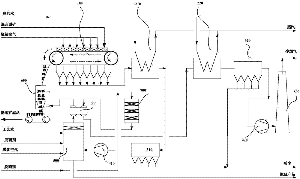
[0028] A steel factory has a 360m 2 The sintering machine emits 1.2 million Nm of flue gas per hour during normal production 3 , applied as figure 1 The shown iron ore sintering system includes a sintering machine 100, a sinter cooler 600 and a smoke stack 800, and also includes two waste heat boilers, two dust collectors, a flue gas desulfurization tower, a flue gas denitrification reactor and two Induced fans, respectively as shown in the figure: the first waste heat boiler 210, the second waste heat boiler 220, the first dust collector 310 and the second dust collector 320, a flue gas desulfurization tower 500, a flue gas denitrification reactor 700, the second An induced draft fan 410 and a second induced draft fan 420. The downstream of the sintering machine 100 is sequentially connected to the first waste heat boiler 210, the first dust collector 310, the first induced draft fan 410, and the flue gas desulfurization tower through the flue gas pipeline. 500, sinter cool...

Embodiment 2

[0041] A steel plant application such as figure 1 The iron ore sintering system shown is different from Embodiment 1 in that in order to improve the desulfurization efficiency of sintering flue gas, the flue gas desulfurization tower 500 is a wet scrubber structure. Using the same iron ore sintering method as in Example 1, the sulfur dioxide content of the inlet flue gas of the exhaust chimney 800 is further reduced to 30mg / Nm 3 the following.

Embodiment 3

[0043] A steel plant application such as figure 1 A kind of iron ore sintering system shown is different from embodiment 1 in that the iron ore sintering method adopted comprises the following steps:

[0044] (1) Iron ore sintering: the raw ore with the mixed formula is added to the crawler from the head of the sintering machine 100, and then a layer of material with a certain thickness is formed through cloth, and sintering starts after ignition, and the sintering air is sucked into the material layer, the track moves at a certain speed, so that the sintered material layer moves from the head to the tail, and completes the entire sintering process; at the same time, the flue gas formed by sintering contains sulfur dioxide, NO x , dust and other pollutants, which are divided into two streams of flue gas, flue gas at the nose and tail flue gas. The content of sulfur dioxide is 1500–2600mg / Nm 3 ,NO x The content is 400–550mg / Nm 3 between;

[0045] (2) Heat recovery from sin...


PUM


Abstract

The invention relates to an iron ore sintering system and method. The iron ore sintering system comprises a sintering machine (100), a sinter cooler (600) and a smoke chimney (800) and further comprises a first waste heat boiler (210), a second waste heat boiler (220), a first dust collector (310), a second dust collector (320), a smoke desulfurization tower (500), a smoke denitration reactor (700), a first induced draft fan (410) and a second induced draft fan (420). The downstream portion of the sintering machine (100) is sequentially connected with a first waste heat boiler (210), the first dust collector (310), the first induced draft fan (410), the smoke desulfurization tower (500), the sinter cooler (600) and the smoke denitration reactor (700) which are used for sintering smoke and the second waste heat boiler (220), the second dust collector (320), the second smoke induced draft fan (420) and the smoke chimney (800) which are used for cooling the smoke through a smoke pipeline. Compared with the prior art, the iron ore sintering system has the beneficial effects that the total smoke discharge is small, the energy utilization efficiency is high, the desulfurization and denitration efficiency is high, the exhaust smoke temperature is high, and the visibility is low.

Description

technical field [0001] The invention belongs to the technical fields of steelmaking and environmental protection, and in particular relates to an iron ore sintering system and method. Background technique [0002] The iron and steel industry is an important part of my country's industry, and a large amount of air pollutants are produced in the production process. Among them, iron ore sintering is one of the most important process units in modern steel production, and it is also a link with the largest energy consumption and the largest pollutant discharge. [0003] The energy consumption of the sintering process accounts for about 10% of the total energy consumption of steel production. Waste heat recovery for this process is very important and is the main direction of energy saving and consumption reduction in the steel industry in the future. Profound significance. Generally, the amount of flue gas emitted by one ton of steel from the sintering process is 2500–4000Nm 3 ...

Claims


Application Information

Patent Timeline
IPC IPC(8): F27B21/00F27D17/00
CPCF27B21/00F27D17/004F27D17/008F27D2017/006Y02P10/25
Inventor 肖文德李学刚娄爱娟
Owner SHANGHAI JIAO TONG UNIV
Why Eureka
Try Eureka