Ceramic tube inner surface polishing device and method

A technology for inner surface polishing and ceramic tubes, which is applied in the direction of surface polishing machine tools, grinding/polishing equipment, grinding machines, etc. It can solve the problems of easy deep scratches on the surface, difficult control of surface quality, and unsatisfactory processing effects. Achieve the effects of reducing uneven grinding, increasing flexibility, and promoting tumbling

Active Publication Date: 2017-09-22
UNIV OF SCI & TECH LIAONING
4 Cites 24 Cited by

AI-Extracted Technical Summary

Problems solved by technology

In order to improve the efficiency of magnetic grinding, auxiliary polishing tools are usually added inside the pipe fittings to increase the magnetic induction intensity in a certain space, thereby increasing the grinding pressure of magnetic abrasive particles. The rigidit...

Method used

[0039] When the present invention utilizes the magnetic grinding method to process the inner surface of the ceramic tube workpiece, the characteristics of the magnetic field distribution and the staggering of the grinding track are used, which is more conducive to reducing the roughness of the inner surface of the tube and obtaining better surface quality. The invention utilizes the rotation effect of the auxiliary magnetic pole 8 to promote the tumbling and replacement of the magnetic abrasive particles,...

Abstract

The invention relates to the technical field of ceramic tube inner surface ultra-precision machining, in particular to a ceramic tube inner surface polishing device and method. The ceramic tube inner surface polishing device comprises a lathe, a magnetism gathering device, a peripheral magnetic pole, a peripheral magnetic pole support, an auxiliary magnetic pole, an L-shaped bevel gear angle rotator, a transmission shaft, an auxiliary magnetic pole support, a high-speed motor, a high-speed motor bracket and a photoelectric limit switch. The magnetism gathering device, the peripheral magnetic pole and the peripheral magnetic pole support are fixed to a sliding box a of the lathe. The high-speed motor, the transmission shaft, the L-shaped bevel gear angle rotator and the auxiliary magnetic pole are connected in sequence and are fixed to a sliding box b of the lathe. A ceramic tube generates rotational motion under the action of the lathe. The high-speed motor drives the auxiliary magnetic pole to rotate. The auxiliary magnetic pole and the peripheral magnetic pole synchronously conduct axial feeding. Magnetic grinding particles and the inner surface of the ceramic tube part move relatively, so that ultra-precision machining of the inner surface of the ceramic tube is completed. The ceramic tube inner surface polishing device is high in machining precision and can be widely applied to polishing of inner surfaces of ceramic tubes.

Application Domain

Technology Topic

Image

  • Ceramic tube inner surface polishing device and method
  • Ceramic tube inner surface polishing device and method
  • Ceramic tube inner surface polishing device and method

Examples

  • Experimental program(1)

Example Embodiment

[0027] The specific embodiments of the present invention will be further described below in conjunction with the drawings:
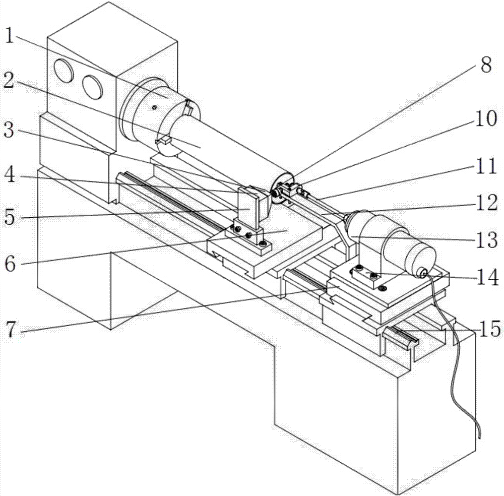
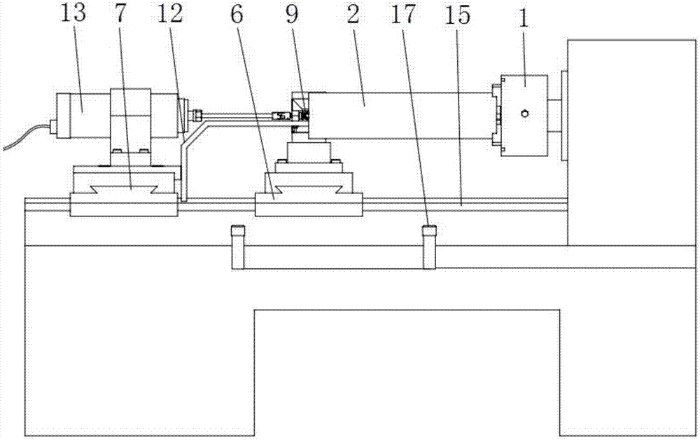
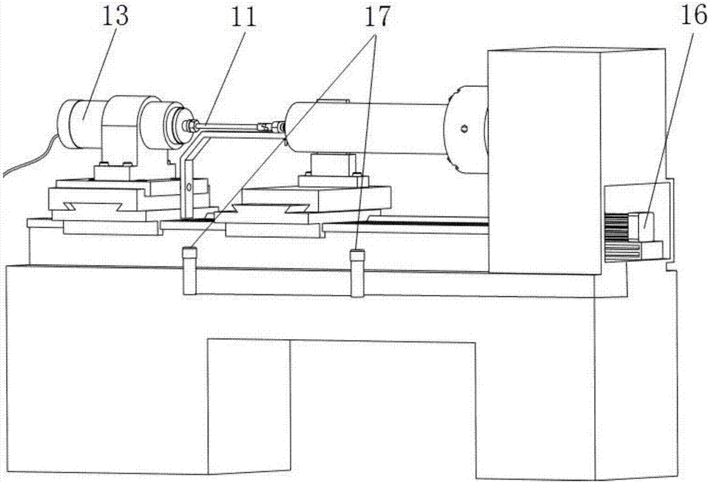
[0028] Such as Figure 1-3 As shown, a ceramic tube inner surface polishing device includes a lathe 1, a magnetization device 3, a peripheral magnetic pole 4, a peripheral magnetic pole support 5, an auxiliary magnetic pole 8, an L-shaped bevel gear corner device 10, a drive shaft 11, an auxiliary magnetic pole support 12, High-speed motor 13, high-speed motor bracket 14, photoelectric limit switch 17.
[0029] The magnetization device 3 and the outer magnetic pole 4 are fixed on the outer magnetic pole bracket 5, and the outer magnetic pole bracket 5 is fixed on the slide box a6 of the lathe 1. The high-speed motor 13, the transmission shaft 11, the L-bevel gear angler 10, and the auxiliary magnetic pole 8 are connected in sequence, and the high-speed motor 13 drives the auxiliary magnetic pole 8 to rotate, and the transmission ratio is 1:1. The high-speed motor 13 is installed on the high-speed motor bracket 14, and the height motor bracket 14 is fixed on the carriage b7 of the lathe 1. The transmission shaft 11 and the L-shaped bevel gear corner device 10 are fixed on the carriage b7 of the lathe 1 through the auxiliary magnetic pole bracket 12.
[0030] The slide box a6 and the slide box b7 are installed on the screw 15 of the lathe 1, and are driven by the screw 15 and the screw motor 16. The photoelectric limit switch 17 is installed on both sides of the bottom of the slide box a6. When the slide box a6 contacts the photoelectric limit switch 17, the screw motor 16 changes the direction of rotation, and the slide box a6 moves in the opposite direction to realize the slide box a6. Perform a reciprocating linear motion between the two photoelectric limit switches 17. The slide box a6 and the slide box b7 are synchronously reciprocated linearly along the screw rod.
[0031] During processing, the ceramic tube 2 is clamped on the three-jaw chuck of the lathe 1, and the auxiliary magnetic pole 8 is placed inside the ceramic tube 2. Such as Figure 4 with 5 As shown, the ceramic tube 2 produces a rotary motion under the action of the lathe 1, the peripheral magnetic pole 4 is fed along the axis of the lathe screw 15, and the high-speed motor 13 drives the auxiliary magnetic pole 8 to rotate and feed synchronously with the peripheral magnetic pole 4. The water-based grinding fluid is uniformly filled between the auxiliary magnetic pole 8 and the inner surface of the ceramic tube 2, and the magnetic grinding particles form a relative movement with the inner surface of the ceramic tube 2 workpiece, thereby completing the ultra-precision machining of the inner surface of the ceramic tube 2.
[0032] Such as Figure 1-5 As shown, the polishing method based on the ceramic tube inner surface polishing device specifically includes the following steps:
[0033] (1) Clamp the ceramic tube 2 workpiece on the three-jaw chuck of the lathe 1, and use a concentricity measuring instrument to ensure that the ceramic tube 2 workpiece is coaxial with the height motor 13 and the drive shaft 11;
[0034] (2) Leave a machining gap of 2mm between the inner surface of the ceramic tube 2 workpiece and the auxiliary magnetic pole 8;
[0035] (3) Mix the magnetic abrasive particles with a particle size of 200um and the water-based abrasive at a volume ratio of 1:3, and evenly fill them into the processing gap;
[0036] (4) The spindle drive motor of the lathe 1 drives the ceramic tube 2 to rotate at a speed of 1500r/min through the three-jaw chuck;
[0037] (5) At the same time, under the control of the screw motor 16 and the photoelectric switch 17, the slide box b7 and the slide box a6 realize synchronous reciprocating linear motion at a speed of 80mm/min;
[0038] (6) After the auxiliary magnetic pole 8 penetrates into the ceramic tube 2, the magnetic abrasive particles move relative to the inner surface of the ceramic tube, and the inner surface of the ceramic tube is polished under the action of squeezing and scratching.
[0039] When processing the inner surface of the ceramic tube workpiece by the magnetic grinding method, the invention utilizes the characteristics of the magnetic field distribution and the staggered grinding track, which is more conducive to reducing the inner surface roughness of the tube and obtaining better surface quality. The invention utilizes the rotation effect of the auxiliary magnetic pole 8 to promote the tumbling and replacement of magnetic abrasive particles, and improve the processing efficiency of grinding and the utilization rate of magnetic abrasive particles. After the rotation auxiliary magnetic pole 8 is added in the present invention, the overall flexibility of the magnetic particle brush composed of magnetic abrasive particles is increased, and the uneven grinding caused by the vibration of the auxiliary magnetic pole is reduced, and the deeper scratches caused by the poor tumbling performance of the magnetic abrasive particles, etc. Processing defects.
[0040] The above are only preferred specific embodiments of the present invention, but the protection scope of the present invention is not limited to this. Anyone familiar with the technical field within the technical scope disclosed by the present invention, according to the technical solution of the present invention The equivalent replacement or change of the inventive concept thereof shall be covered by the protection scope of the present invention.

PUM

PropertyMeasurementUnit
Particle size180.0 ~ 260.0µm
tensileMPa
Particle sizePa
strength10

Description & Claims & Application Information

We can also present the details of the Description, Claims and Application information to help users get a comprehensive understanding of the technical details of the patent, such as background art, summary of invention, brief description of drawings, description of embodiments, and other original content. On the other hand, users can also determine the specific scope of protection of the technology through the list of claims; as well as understand the changes in the life cycle of the technology with the presentation of the patent timeline. Login to view more.

Similar technology patents

Method for manufacturing titanium-and-titanium alloy high-pressure gas cylinder

PendingCN110465780AEliminate wrinklesReduce roughnessVessel manufacturingPressure vesselsTitaniumHigh pressure
Owner:BAOJI FANMEI MATERIAL TECH

Classification and recommendation of technical efficacy words

  • Good surface quality
  • Reduce roughness

Method for improving strength of glass

InactiveCN101648776AImprove surface conditionGood surface qualityTransmittanceCorrosion
Owner:BYD CO LTD

Composite material member with surface function layer and VIMP preparation method thereof

InactiveCN101830095AFast impregnationGood surface qualitySynthetic resin layered productsSurface functionMaterial system
Owner:NAT UNIV OF DEFENSE TECH
Why Eureka
Try Eureka