A self-catalytic denitrification system for sintering dust coupled with waste heat of sintering dust

A technology of self-catalysis and soot, which is applied in the direction of chemical instruments and methods, separation methods, and separation of dispersed particles, can solve the problems of low equipment investment and operating costs, difficult disposal of waste catalysts, and high operating costs, and achieve equipment investment and operating costs Low cost, reduced investment in denitrification equipment, and full use of waste heat in the system

Active Publication Date: 2020-06-02
武汉钢铁有限公司 +2
View PDF13 Cites 0 Cited by
  • Summary
  • Abstract
  • Description
  • Claims
  • Application Information

AI Technical Summary

Problems solved by technology

[0006] The purpose of the present invention is to solve the above-mentioned technical problems, aiming at the existing problems such as complex sintering flue gas denitration system, long process route, large investment, high operating cost, and difficult disposal of waste catalysts, etc., to provide a simple system that does not need to purchase catalysts to realize Sintering soot autocatalytic denitrification system with effective denitrification, high waste heat recovery rate, energy saving, small footprint, low equipment investment and operating costs

Method used


Image

  • A self-catalytic denitrification system for sintering dust coupled with waste heat of sintering dust

Examples


Embodiment Construction

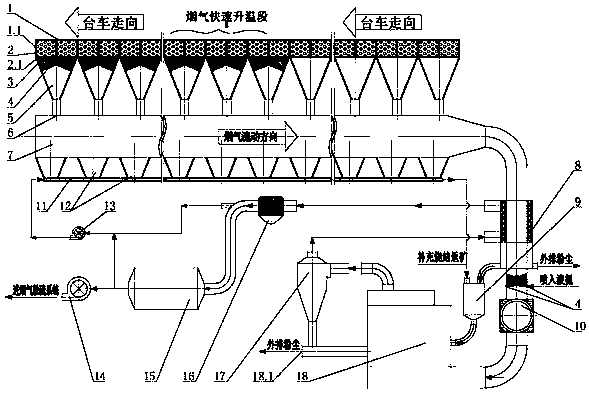
[0028] The system of the present invention will be further explained below in conjunction with the accompanying drawings:

[0029] The bottom of the trolley 1.1 of the sintering machine 1 is provided with a bellows 5, the outlet at the bottom of the bellows 5 is connected to the main flue 7, and the sintering machine 1 is sequentially divided into an ignition section, a head section, a flue gas rapid heating section and a There are 4 areas in the tail section, the ignition section is located at the front end of the sintering machine 1, and this area occupies 1-2 bellows length; the nose section is located in the front half of the sintering machine after the ignition section and extends to the middle of the sintering machine. The area accounts for 35-45% of the total length of the sintering machine; the rapid heating section of the flue gas is located in the middle of the sintering machine towards the tail of the machine, and this area occupies 2-4 lengths of the bellows; the ta...


PUM


Abstract

The invention relates to a sintering smoke self-catalyzing denitrifying system by coupling and utilizing residual heat of sintering smoke, which solves the problems of large investment, high running cost and lower denitrifying efficiency in the existing denitrifying system. The sintering smoke self-catalyzing denitrifying system adopts the technical scheme that the sintering smoke self-catalyzing denitrifying system comprises a sintering machine, wherein air bellows are arranged under a trolley of the sintering machine; an exit of the bottom part of each air bellow is communicated with a main flue; the sintering machine is sequentially provided with an ignition section, a machine head section, a flue gas quick heating section and a machine tail section along the moving direction of the trolley; the main flue is sequentially connected with a denitrifying reactor of a fluidized bed through a denitrifying flue gas heat exchanger shell or tube, and a flue gas heater; liquid ammonia spray nozzles are respectively arranged in the air bellows under the machine tail section to the flue gas quick heating section area, and in the flue gas exit pipeline of the flue gas heater. The sintering smoke self-catalyzing denitrifying system has the advantages that the system is simple, the additional purchase of the catalyst is avoided, the effective denitrifying and sintering process is realized, the recycling rate of residual heat is high, the energy-saving and consumption-reducing effects are realized, the land occupation area is small, and the equipment investment and running cost are low.

Description

technical field [0001] The invention relates to a flue gas denitrification process in the field of environmental protection, in particular to a sintering fume autocatalytic denitrification system which couples and utilizes the waste heat of sintering fume. Background technique [0002] Sintering flue gas is a gas containing a variety of polluting components produced during the ignition, melting, and high-temperature sintering of various powdery iron-containing raw materials, fuels, and fluxes. The sintering flue gas has a large amount of flue gas (4000-6000m 3 / ton of sinter), large temperature changes (120-200°C), high CO concentration (0.5-2.0%), SO 2 Concentration changes greatly (1000-3000mg / Nm 3 ), NO x Low concentration (300-500 mg / Nm 3 ), high moisture content (7-12%) and high oxygen content (15-18%). Compared with power plant flue gas, it has many characteristics of its own, its flue gas composition is more complex, its changes fluctuate more, and its treatment...

Claims


Application Information

Patent Timeline
Patent Type & Authority Patents(China)
IPC IPC(8): B01D53/90B01D53/56
CPCB01D53/343B01D53/8631B01D53/90B01D2251/2062B01D2255/20738B01D2258/0283
Inventor 吴高明吴晓晖秦林波卫书杰
Owner 武汉钢铁有限公司
Why Eureka
Try Eureka