Semiconductor device structure and preparation method thereof
A device structure and semiconductor technology, applied in the direction of semiconductor devices, electric solid devices, electrical components, etc., can solve the problem of high contact resistance and achieve the effect of low contact resistance
- Summary
- Abstract
- Description
- Claims
- Application Information
AI Technical Summary
Problems solved by technology
Method used
Image
Examples
Embodiment 1
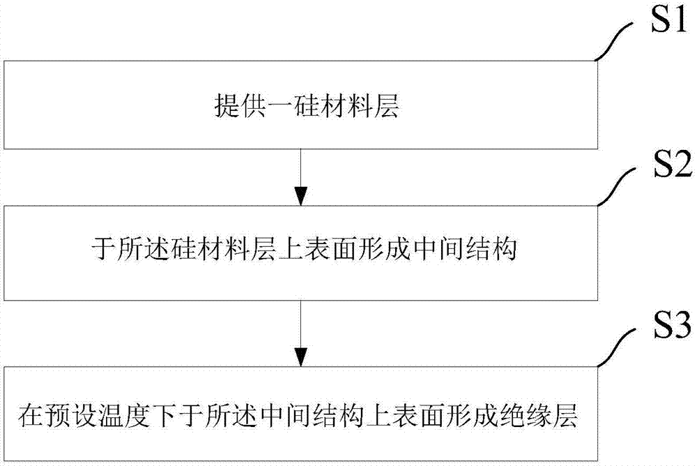
[0065] see Figure 1 ~ Figure 4 , the present embodiment provides a method for preparing a semiconductor device structure, the preparation method comprising the following steps:
[0066] Such as figure 1 S1 and figure 2 Shown, carry out step 1), provide a silicon material layer 11;
[0067] Specifically, the silicon material layer 11 can be any silicon-containing material, including single crystal silicon, polycrystalline silicon, amorphous silicon, or silicon germanium material, such as the silicon material layer 11 is a polycrystalline silicon germanium layer, the silicon The material of the material layer 11 may also be a doped material of any of the above materials, such as intrinsic silicon, P-type silicon, N-type silicon, etc., which are not specifically limited here. Of course, the silicon material layer 11 can also be a laminated structure of at least two layers of materials, such as a laminated structure composed of a polysilicon layer doped with N-type impurities...
Embodiment 2
[0085] see Figure 5 , this embodiment provides a method for fabricating a semiconductor device structure. The difference between the second embodiment and the first embodiment is that in step 2), the intermediate structure 12 further includes a first metal nitride layer 122, and the A first metal nitride layer 122 is formed between the first metal layer 121 and the second metal layer 124 .
[0086] Specifically, the material of the first metal nitride layer 122 includes but not limited to tantalum nitride, palladium nitride, platinum nitride, cobalt nitride, zirconium nitride, nickel nitride, titanium nitride, molybdenum nitride, And the first metal nitride layer 122 is formed by physical vapor deposition (PVD) method (such as evaporation, electroplating or sputtering, etc.), chemical vapor deposition (CVD) method or atomic layer deposition (ALD) method. In addition, the thickness of the first metal nitride layer 122 is 3-50 nm, preferably 5-30 nm or 10-20 nm. In this embodi...
Embodiment 3
[0100] see Figure 6 , this embodiment provides a method for fabricating a semiconductor device structure. The difference between the third embodiment and the second embodiment is that in step 2), the intermediate structure 12 further includes a second metal nitride layer 125, and the The second metal nitride layer 125 is formed between the first metal nitride layer 122 and the second metal layer 124 .
[0101] Specifically, the material of the second metal nitride layer 125 may be tungsten nitride, or W / Si / N-based materials, etc., and the second metal nitride layer 125 is formed by physical vapor deposition (PVD) (such as evaporation, electroplating or sputtering, etc.), chemical vapor deposition (CVD) or atomic layer deposition (ALD) methods. In addition, the thickness of the second metal nitride layer 125 is 1-6 nm, preferably 2-4 nm. In this embodiment, the thickness of the second metal nitride layer 125 is 3 nm.
[0102] It should be noted that, in this embodiment, poly...
PUM
| Property | Measurement | Unit |
|---|---|---|
| thickness | aaaaa | aaaaa |
| thickness | aaaaa | aaaaa |
| thickness | aaaaa | aaaaa |
Abstract
Description
Claims
Application Information
 - R&D
- Intellectual Property
- Life Sciences
- Materials
- Tech Scout
- Unparalleled Data Quality
- Higher Quality Content
- 60% Fewer Hallucinations
Browse by: Latest US Patents, China's latest patents, Technical Efficacy Thesaurus, Application Domain, Technology Topic, Popular Technical Reports.
© 2025 PatSnap. All rights reserved.Legal|Privacy policy|Modern Slavery Act Transparency Statement|Sitemap|About US| Contact US: help@patsnap.com


