Powder metallurgy high-speed steel valve seat for clean fuel engine and production process of powder metallurgy high-speed steel valve seat

A technology of powder metallurgy and high-speed steel, applied in the field of clean fuel engine powder metallurgy high-speed steel valve seat and its preparation, can solve the problems of clean fuel engine powder metallurgy valve seat wear and other problems, achieve reasonable composition ratio, stable performance, and material source simple effect

Active Publication Date: 2017-10-20
HUBEI UNIV OF AUTOMOTIVE TECH
View PDF4 Cites 10 Cited by
  • Summary
  • Abstract
  • Description
  • Claims
  • Application Information

AI Technical Summary

Problems solved by technology

[0009] In order to solve the problem of serious wear of powder metallurgy valve seat of clean fuel engine, the purpose of the p

Method used


Image

  • Powder metallurgy high-speed steel valve seat for clean fuel engine and production process of powder metallurgy high-speed steel valve seat
  • Powder metallurgy high-speed steel valve seat for clean fuel engine and production process of powder metallurgy high-speed steel valve seat
  • Powder metallurgy high-speed steel valve seat for clean fuel engine and production process of powder metallurgy high-speed steel valve seat

Examples


Embodiment 1

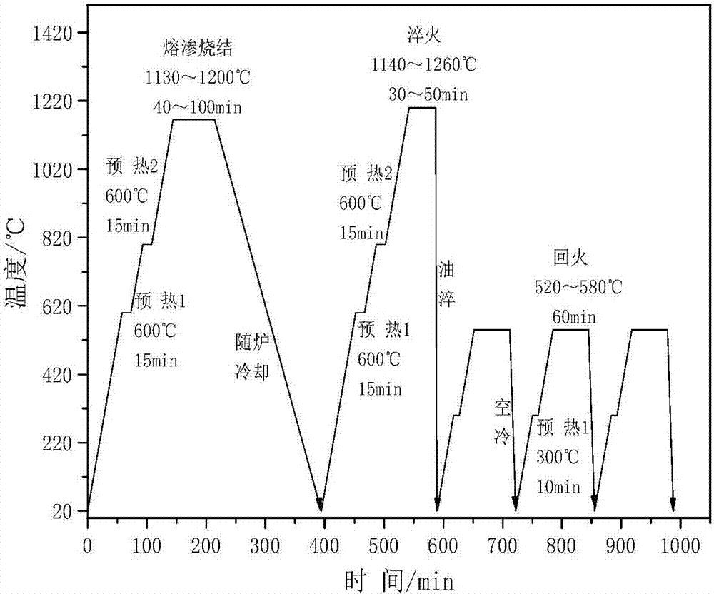
[0036] (1) Carry out direct infiltration sintering in a vacuum sintering furnace, heat preservation at 600°C and 800°C for 15 minutes, heat preservation at 1165°C for 40-100 minutes, and a heating rate of 10°C / min, and cool with the furnace after infiltration sintering is completed.

[0037] (2) Heat to 1140°C in a vacuum quenching furnace, keep it warm for 30-50 minutes, and the heating rate is 10°C / min, quench in warm oil (about 50°C), then heat to 300°C and keep it for 10 minutes, and keep it at 520°C for 60 minutes, Tempering treatment 3 times.

[0038] (3) Machining into finished products

Embodiment 2

[0040] (1) Carry out direct infiltration sintering in a vacuum sintering furnace, heat preservation at 600°C and 800°C for 15 minutes, heat preservation at 1165°C for 40-100 minutes, and a heating rate of 10°C / min, and cool with the furnace after infiltration sintering is completed.

[0041] (2) Heat to 1180°C in a vacuum quenching furnace, keep it warm for 30-50min, and the heating rate is 10°C / min, quench it in warm oil (about 50°C), then heat it to 300°C and keep it for 10min, and keep it at 580°C for 60min, Tempering treatment 3 times.

[0042] (3) Machining into finished products

Embodiment 3

[0044] (1) Carry out direct infiltration sintering in a vacuum sintering furnace, heat preservation at 600°C and 800°C for 15 minutes, heat preservation at 1165°C for 40-100 minutes, and a heating rate of 10°C / min, and cool with the furnace after infiltration sintering is completed.

[0045] (2) Heat to 1220°C in a vacuum quenching furnace, keep it warm for 30-50 minutes, and the heating rate is 10°C / min, quench in warm oil (about 50°C), then heat to 300°C and keep it for 10 minutes, and keep it at 520°C for 60 minutes, Tempering treatment 3 times.

[0046] (3) Machining into finished products

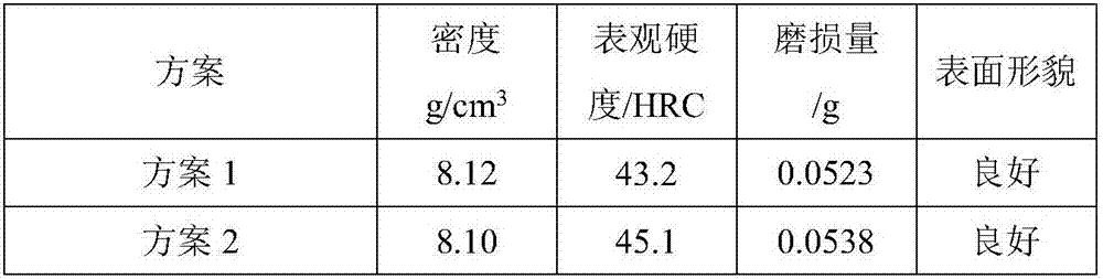
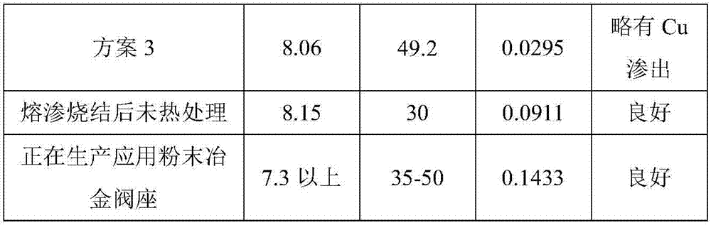
[0047] Abrasion resistance test. Test conditions: The wear test is carried out on the M-2000 friction and wear testing machine, using disc-pin wear, resin alumina material as the abrasive, the load is 120N, the friction speed is 200r / min, and the wear time is 30min.

[0048] The specific index of the powder metallurgy high-speed steel valve seat prepared by the technical solution of ...


PUM


Abstract

The invention discloses a powder metallurgy high-speed steel valve seat for a clean fuel engine and a production process of the powder metallurgy high-speed steel valve seat. With W6Mo5Cr4V2 high-speed steel powder as a base body material, Cu, Co-Cr-Mo and Fe-Mo hard particles are added, and the hard particles comprise, by mass percentage, 45%-57% of W6Mo5Cr4V2, 13%-17% of Co-Cr-Mo, 4%-7% of Fe-Mo, 17%-22% of Cu and 2%-3% of a solid lubricant and easy-to-cut components. According to the powder metallurgy high-speed steel valve seat, by the adoption of an infiltration sintering and heat treatment technology, the density of the powder metallurgy high-speed steel valve seat is increased, the hardness, wear resistance and the like of the powder metallurgy high-speed steel valve seat are improved; and on the one hand, stable alloy tempered martensite and fine dispersed secondary alloy carbide can be obtained, and on the other hand, the bonding of a base body and the hard particles is firmer, and the hard particles are not likely to be peeled off from the base body during frictional wear. By the adoption of the infiltration sintering and heat treatment technology, the density of the material is increased, and the hardness, wear resistance and the like of the material are improved.

Description

technical field [0001] The invention relates to the technical field of metal materials, in particular to a powder metallurgy high-speed steel valve seat for a clean fuel engine and a preparation process thereof. Background technique [0002] The valve seat of the valve is an important part of the engine. It cooperates with the valve to control the entry and exit of gas and exhaust gas. Its performance directly affects the power and economy of the engine. The original fuel oil valve seat has been working under high temperature, high impact load, hot corrosion atmosphere and other environments for a long time, and the working conditions are very harsh. Since the beginning of the 21st century, the use of clean fuels such as CNG and LPG in engines has become the key support direction of my country's new energy strategy. However, after engines use clean fuels such as CNG and LPG, the lubricating components of the fuel are reduced, and the valves and valve seats are in direct cont...

Claims


Application Information

Patent Timeline
IPC IPC(8): C22C38/22C22C38/30C22C38/20C22C38/38C22C38/04C22C38/60C22C38/24C22C33/02B22F1/00C21D1/18C21D9/00B22F3/02B22F3/10B22F3/24
CPCC21D1/18C21D9/0068C22C33/0278C22C33/0285C22C38/04C22C38/20C22C38/22C22C38/24C22C38/30C22C38/38C22C38/60B22F3/02B22F3/10B22F3/24B22F2003/248B22F1/105
Inventor 罗成肖紫圣
Owner HUBEI UNIV OF AUTOMOTIVE TECH
Why Eureka
Try Eureka