Compression calcining type oil shale dry-distillation system

An oil shale and calcined technology, applied in the field of compression calcined oil shale carbonization system, can solve the problems of unutilized latent heat, large maintenance, large power consumption, etc., achieve reduced grinding equipment configuration, low loss graded carbonization , The effect of reducing energy costs

Pending Publication Date: 2017-10-27
JIANGSU PENGFEI GROUP
View PDF0 Cites 2 Cited by
  • Summary
  • Abstract
  • Description
  • Claims
  • Application Information

AI Technical Summary

Problems solved by technology

[0004] There are three typical devices for carbonization of small particle oil shale in foreign countries, one is the ATP furnace (Alberea-Taciuk Processor) in Australia, which is a solid heat carrier rotary retort furnace with huge equipment, complex structure, large power consumption, The operation is unstable, and the furnace is often shut down for maintenance. The operating rate is only about 50%, and the longest continuous operation is only 96 days.
One is the Galoter furnace in Estonia, which can process 0-25mm oil shale, with a processing capacity of 3000t / d. The problem with the equipment is that the operation rate is not high, the proportion of heavy oil is large, and there are mechanical operations, oil and gas Dust removal and flue gas dust removal and other issues
The third is the Tosco-II oil shale dry distillation technology developed by Tosco Corporation of the United States, which is used to process small particle oil shale. This system uses ceramic balls as the heat carrier, and the oil recovery rate reaches 90%. The problems with this equipment are: : High investment in equipment, large amount of maintenance, low thermal efficiency, and the latent heat (fixed carbon) in oil shale semi-coke is not utilized
The device uses thermal cycle gas to exchange heat with oil shale, part of the heat is lost in the external pipeline circulation, the heat utilization rate is low, and the equipment structure is complex

Method used


Image

  • Compression calcining type oil shale dry-distillation system

Examples


Embodiment Construction

[0023] In order to deepen the understanding of the present invention, the present invention will be further described below in conjunction with the accompanying drawings and embodiments, which are only used to explain the present invention and do not limit the protection scope of the present invention.

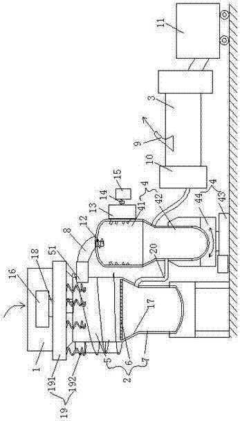
[0024] like figure 1 As shown, a compressed calcined oil shale retort system includes a crushing device 1, a compression and classification device 2, a sandblasting retort device 4, a filter 10, an oil and gas separation device 3, an oil and gas dust collector 9, and an oil collection device connected in sequence 11, wherein: the compression and classification device 2 is a cylindrical structure, and it includes a capsule-type classification compression chamber 5, a fixed mesh screen 6, and a first-stage dry distillation calciner 7 connected sequentially from top to bottom, wherein the capsule-type classification compression chamber 5 The diameter is greater than the diameter ...


PUM


Abstract

The invention discloses a compression calcining type oil shale dry distillation system, which comprises a crushing device, a compression classification device, a sandblasting dry distillation device, a filter, an oil gas separation device, an oil gas dust collector, and an oil collection device connected in sequence, wherein: compression classification The device includes sequentially connected capsule-type grading compression chambers, fixed mesh screens, and first-stage dry distillation and calcining chambers. The capsule-type grading compression chambers are equipped with vertically telescopic power sources, telescopic sleeves, and automatic recovery devices. The outlet of small grains of oil shale passes through The conveying pipe transports the small particle oil shale to the sandblasting and retorting device, and the sandblasting and retorting device includes a vertical sandblasting section and a secondary calcining device; the primary retorting and calcining chamber is also connected to the secondary calcining device. The dry distillation system of the present invention compresses and grades oil shale according to particle size, and is accompanied by sandblasting in the second stage of calcination, and heat energy can be shared between the two stages of calcination. It is a highly efficient, low-loss graded dry distillation system for calcination.

Description

technical field [0001] The invention relates to the technical field of oil shale dry distillation system, in particular to a compression calcined oil shale dry distillation system. Background technique [0002] The reaction process of thermal decomposition of solid or organic matter under air-isolated conditions is called dry distillation. The result of dry distillation is to generate various gases, steam and solid residues. The present invention mainly uses oil sand as the main dry distillation raw material. The slag containing combustible solid product carbon residue obtained by dry distillation is called semi-coke. [0003] In the current dry distillation system of solid heat carrier, the raw material enters the reactor, the semi-coke enters the semi-coke calcination equipment from the reactor, and the heat carrier enters the reactor from the semi-coke calcination equipment, all through the material itself as a sealing medium to prevent the inlet and outlet of the reactor...

Claims


Application Information

Patent Timeline
Patent Type & Authority Applications(China)
IPC IPC(8): C10B53/06C10B57/02C10B47/30
CPCC10B53/06C10B47/30C10B57/02
Inventor 王家安
Owner JIANGSU PENGFEI GROUP
Why Eureka
Try Eureka