A self-catalyzed denitrification process of sintering dust coupled with waste heat of sintering dust

A self-catalysis and soot technology, applied in chemical instruments and methods, separation methods, dispersed particle separation, etc., can solve the problems of large investment in sintering flue gas denitrification, high operating costs, difficult disposal of waste catalysts, etc., and reduce the investment in denitrification equipment. , the effect of low equipment investment and operating costs, and broad market application prospects

Active Publication Date: 2020-04-03
WUHAN UNIV OF SCI & TECH +2
View PDF4 Cites 0 Cited by
  • Summary
  • Abstract
  • Description
  • Claims
  • Application Information

AI Technical Summary

Problems solved by technology

[0007] The purpose of the present invention is to solve the above-mentioned technical problems, aiming at the problems of large investment, high operation cost, and difficult disposal of waste catalysts in existing sintering flue gas denitrification, to provide a simple system, no outsourcing of catalysts, and high efficiency of waste heat recovery in the sintering process. , energy saving and consumption reduction, small footprint, low flue gas denitrification equipment investment and operating costs, coupled with the sintering dust autocatalytic denitrification process that utilizes the waste heat of sintering dust

Method used


Image

  • A self-catalyzed denitrification process of sintering dust coupled with waste heat of sintering dust

Examples


Embodiment Construction

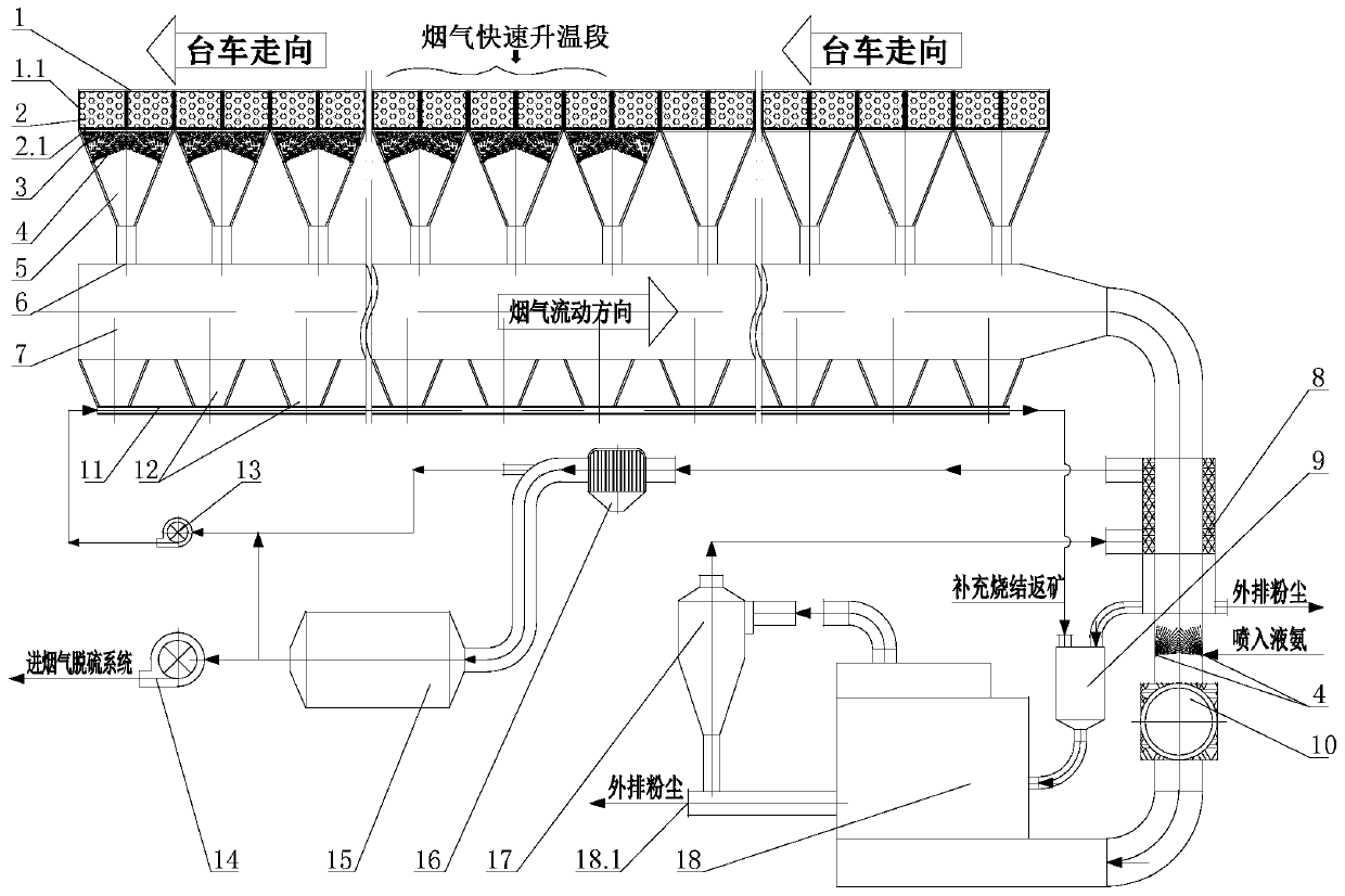
[0032] The system of the present invention will be further explained below in conjunction with the accompanying drawings:

[0033] A bellows 5 is provided under the trolley 1.1 of the sintering machine 1, and the bellows outlet pipe 6 at the bottom of the bellows 5 is connected to the main flue 7, and the sintering machine 1 is sequentially divided into an ignition section, a head section, and a flue gas rapid flow along the traveling direction of the trolley. There are 4 areas of heating section and machine tail section. The ignition section is located at the front end of the sintering machine 1, and this area occupies 1-2 windbox lengths; the head section is located in the front half of the sintering machine after the ignition section and extends to the sintering machine In the middle, this area accounts for 35-45% of the total length of the sintering machine; the rapid heating section of the flue gas is located in the middle of the sintering machine towards the tail, and thi...


PUM


Abstract

The invention relates to an autocatalytic denitrification process of sintering smoke dust by coupling utilization of smoke dust waste heat. According to the technical scheme, sintering smoke dust penetrates a sintering material layer, a bottom layer, a bottom grate of a sintering machine trolley and bellows under the trolley and enters a main flue under the draft action of a high-pressure blower; a sintering machine is divided into an ignition section, a machine head section, a smoke rapid heating section and a machine tail section in the traveling direction of the sintering machine trolley sequentially, the sintering smoke dust flows out of a main flue, passes through a denitrification smoke heat exchanger and a smoke heater sequentially and enters a fluidized bed denitrification reactor; liquid ammonia is sprayed into the bellows under the machine tail section, the bellows under the smoke rapid heating section and a smoke outlet pipe of the smoke heater, so that the sintering smoke dust is subjected to a denitrification reduction reaction with ammonia gas under the catalysis effect of particles which are rich in iron oxide and carried by the sintering smoke dust. The process has the advantages of simple process, no purchased catalyst, high recovery of waste heat, small floor area, low equipment investment and low operation cost, is energy saving and reduces consumption.

Description

technical field [0001] The invention relates to a flue gas denitrification process in the field of environmental protection, in particular to an autocatalytic denitrification process for sintering fume that couples and utilizes the waste heat of sintering fume. Background technique [0002] To reduce SO 2 and NO X pollution, the state has formulated more stringent emission standards. In the coal power industry, separate desulfurization or denitrification technologies have achieved success and achieved industrial applications, such as limestone-gypsum desulfurization technology and selective catalytic reduction (SCR) denitrification technology, whose desulfurization and denitrification efficiency can reach more than 90%. Selective catalytic reduction denitration is the use of ammonia (NH 3 ) as a reducing agent, in the presence of a catalyst, the NO in the flue gas X reduced to N 2 . [0003] However, in terms of desulfurization and denitrification of sintering flue gas...

Claims


Application Information

Patent Timeline
Patent Type & Authority Patents(China)
IPC IPC(8): B01D53/86B01D53/90B01D53/56
CPCB01D53/8625B01D53/90B01D2251/2062B01D2255/20738B01D2258/0283B01D2259/124
Inventor 秦林波吴高明姚茜卫书杰吴晓晖
Owner WUHAN UNIV OF SCI & TECH
Why Eureka
Try Eureka