N type double face battery preparation method

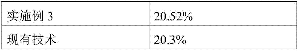
A double-sided cell, N-type technology, applied in the field of solar cells, can solve the problems of affecting the photoelectric conversion efficiency of double-sided cells, incomplete suede structure on the back, and reduced passivation quality, and achieve a uniform front and back nano suede structure, Excellent light trapping performance, improve the effect of FF

Active Publication Date: 2017-11-24
JINKO SOLAR CO LTD +1
View PDF4 Cites 10 Cited by
  • Summary
  • Abstract
  • Description
  • Claims
  • Application Information

AI Technical Summary

Problems solved by technology

[0004] However, in the preparation process of the existing N-type double-sided solar cells, because the back surface is etched by HF / HNO3 to remove BSG (borosilicate glass), the structure of the back texture is incomplete, resulting in poor light trapping effect, and after grid line printing , due to the destruction of the passivation layer, the quality of passivation is reduced, and the recombination on the back is aggravated, which affects Uoc (open circuit voltage), Isc (short circuit current) and FF (fill factor), and finally affects the photoelectric conversion efficiency of the front side of the double-sided battery. The photoelectric conversion efficiency of the front side of the N-type double-sided solar cell prepared by the technology is 20.3%.

Method used


Image

  • N type double face battery preparation method
  • N type double face battery preparation method
  • N type double face battery preparation method

Examples


preparation example Construction

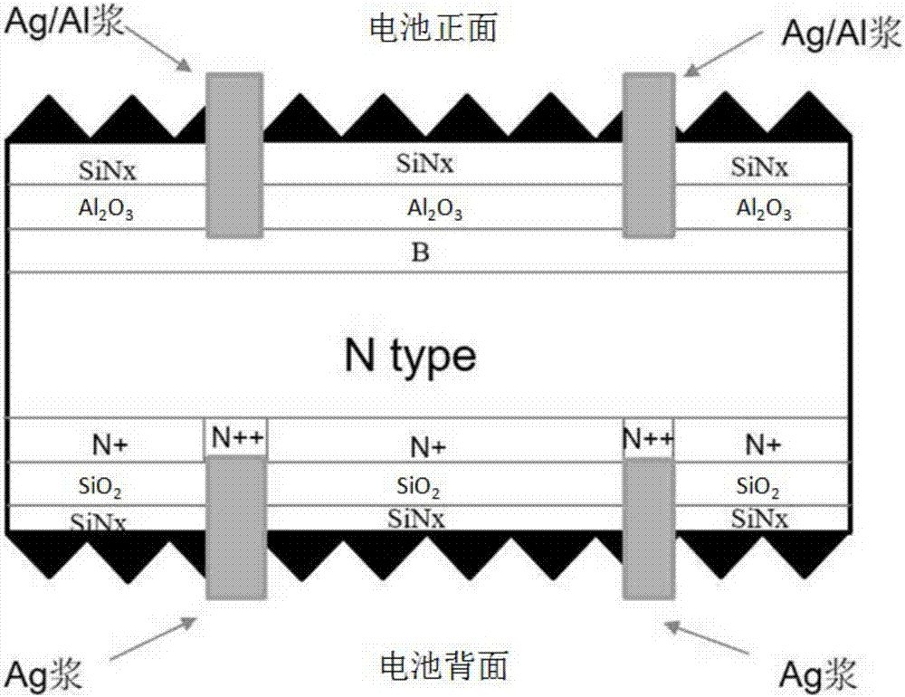
[0031] An embodiment of the present invention provides a method for preparing an N-type double-sided battery, including:

[0032] S11, performing damage treatment on the surface of the N-type silicon wafer;

[0033] Wherein, the damage treatment method can adopt conventional means, for example, treating the N-type silicon wafer with KOH solution to control the weight loss of the silicon wafer to 0.6-0.7 g.

[0034] S12, performing double-sided reactive ion etching on the N-type silicon wafer, so as to prepare a nano-textured surface on the surface of the N-type silicon wafer;

[0035] S13, performing boron diffusion on the front side of the N-type silicon wafer after the back side of the N-type silicon wafer is treated with a SiOx-SiNy mask;

[0036] S14, after removing the SiOx-SiNy mask layer on the back side of the N-type silicon wafer with an HF solution, performing a SiOx-SiNy mask on the front side of the N-type silicon wafer;

[0037] S15, performing SiO on the back s...
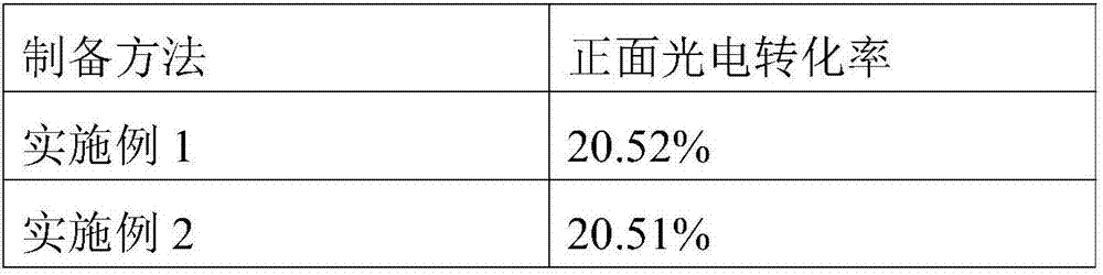
Embodiment 1

[0050] A method for preparing an N-type double-sided battery, comprising:

[0051] S21, performing damage treatment on the surface of the N-type silicon wafer;

[0052] S22, performing double-sided reactive ion etching on the N-type silicon wafer to prepare a nano-textured surface on the surface of the N-type silicon wafer, wherein the reflectivity of the N-type silicon wafer is controlled at 5%;

[0053] S23, after treating the back side of the N-type silicon wafer with a SiOx-SiNy mask, perform boron diffusion on the front side of the N-type silicon wafer, wherein the boron diffusion temperature is 950°C, and the square resistance is controlled at 85-95Ω / Square.;

[0054] S24, after removing the SiOx-SiNy mask layer on the back side of the N-type silicon wafer with an HF solution, and then performing a SiOx-SiNy mask on the front side of the N-type silicon wafer;

[0055] S25, performing SiO on the back side of the N-type silicon wafer 2 layer growth, where the SiO 2 Th...

Embodiment 2

[0062] A method for preparing an N-type double-sided battery, comprising:

[0063] S31, performing damage treatment on the surface of the N-type silicon wafer;

[0064] S32, performing double-sided reactive ion etching on the N-type silicon wafer to prepare a nano-textured surface on the surface of the N-type silicon wafer, wherein the reflectivity of the N-type silicon wafer is controlled at 3%;

[0065] S33, after treating the back side of the N-type silicon wafer with a SiOx-SiNy mask, performing boron diffusion on the front side of the N-type silicon wafer, wherein the boron diffusion temperature is 900° C., and the square resistance is controlled at 80Ω / Squar. ;

[0066] S34, after removing the SiOx-SiNy mask layer on the back side of the N-type silicon wafer with an HF solution, and performing a SiOx-SiNy mask on the front side of the N-type silicon wafer;

[0067] S35, performing SiO on the back side of the N-type silicon wafer 2 layer growth, where the SiO 2 The th...


PUM


Abstract

The invention provides an N type double face battery preparation method comprising the following steps: an N type silicon chip is subjected to double face reactive ion etching operation after undergoing damage processing operation, and therefore a nanometer pile face can be made on a surface; a front face of the N type silicon chip is subjected to boron diffusion operation after a back face of the N type silicon chip undergoes SiOx-SiNy mask layer processing operation; the front face is subjected to the SiOx-SiNy mask layer processing operation after the SiOx-SiNy mask layer on the back face is removed via an HF solution, an SiO2 layer is grown on the back face and used as a mask layer, an N++ window is formed after point perforating operation is performed under a main grid, residual damage during perforation can be removed via use of weak alkali liquor, single face phosphorus diffusion is performed on the back face of the N type silicon chip, an N++ layer is formed at a perforated position, N+ layers are formed at other areas, and the N type silicon chip is subjected to HF processing operation after edge isolation is conducted on the N type silicon chip; the SiOx-SiNy mask layer and borosilicate glass on the front face and phosphorosilicate glass on the back face are removed; RCA cleaning operation is performed; the front face and the back face of the N type silicon chip are respectively subjected to A12O3/SiNx and lamination passivation operation, and sintering operation is conducted after screen printing operation; via the N type double face battery preparation method, Uoc, Isc and FF can be improved; photoelectric conversion efficiency of a front face of a battery can be improved.

Description

technical field [0001] The invention relates to the technical field of solar cells, in particular to a method for preparing an N-type double-sided cell. Background technique [0002] As the greenhouse effect becomes more and more obvious, people pay more and more attention to the ecological environment. As one of the clean energy industries, the solar energy industry is developing rapidly at this stage. Among them, silicon-based batteries are the most widely used, so the improvement of its efficiency has always attracted people's attention. At present, P-type crystalline silicon cells have the advantages of low cost and mature technology, and have occupied a major market share. However, due to the characteristics of light-induced attenuation and low substrate life, P-type cells still have a large bottleneck in terms of high efficiency. [0003] Compared with P-type silicon wafers, N-type silicon wafers have the advantages of high minority carrier lifetime, high tolerance to...

Claims


Application Information

Patent Timeline
Patent Type & Authority Applications(China)
IPC IPC(8): H01L31/18H01L31/068
CPCH01L31/0684H01L31/1804Y02E10/547Y02P70/50
Inventor 廖晖王海涛包健李林东陈伟金浩
Owner JINKO SOLAR CO LTD
Why Eureka
Try Eureka