Carbon dioxide and oxygen gas mixing device and mixed gas combustion-supporting pollution gas zero-emission system

A gas mixing device, carbon dioxide technology, applied in indirect carbon dioxide emission reduction, direct carbon dioxide emission reduction, mixer and other directions, can solve the problems of large volume of nitrogen and nitrogen oxides, reduce combustion thermal efficiency, and difficulty in carbon dioxide, so as to reduce pollution , the effect of alleviating smog and reducing the difficulty of recycling

Active Publication Date: 2020-11-24
张家口新金石科技发展有限公司
View PDF6 Cites 0 Cited by
  • Summary
  • Abstract
  • Description
  • Claims
  • Application Information

AI Technical Summary

Problems solved by technology

However, due to the fact that air participates in combustion in the combustion process, nitrogen in the air accounts for 78.084% of the total volume of air, oxygen accounts for 20.948%, and the sum of other gases accounts for 0.68%. Nitrogen reacts with oxygen and produces a variety of nitrogen oxides, which not only pollute the air but also take away a lot of heat when discharged into the air, reducing the thermal efficiency of combustion, and because the volume of nitrogen in the tail gas is still large , so the concentration of harmful gases is low, and the difficulty of tail gas treatment is quite large
[0004] Since the current exhaust gas treatment system only treats sulfur oxides and nitrogen oxides, a large amount of carbon dioxide is discharged into the air. It is well known that carbon dioxide is a typical greenhouse gas, which causes air pollution and forms a terrible greenhouse. effect, but because the volume occupied by nitrogen and nitrogen oxides in the tail gas is large, and the volume occupied by carbon dioxide is small, it is difficult and costly to recover carbon dioxide in the tail gas

Method used


Image

  • Carbon dioxide and oxygen gas mixing device and mixed gas combustion-supporting pollution gas zero-emission system
  • Carbon dioxide and oxygen gas mixing device and mixed gas combustion-supporting pollution gas zero-emission system
  • Carbon dioxide and oxygen gas mixing device and mixed gas combustion-supporting pollution gas zero-emission system

Examples


Embodiment Construction

[0027] Embodiments of the present invention are described in detail below, examples of which are shown in the drawings, wherein the same or similar reference numerals designate the same or similar elements or elements having the same or similar functions throughout. The embodiments described below by referring to the figures are exemplary only for explaining the present invention and should not be construed as limiting the present invention.

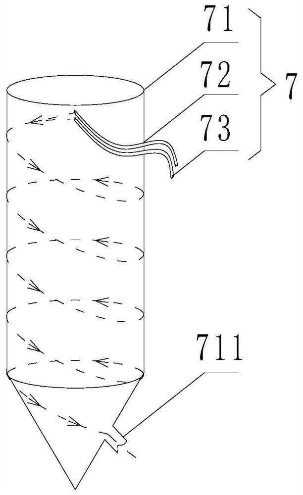
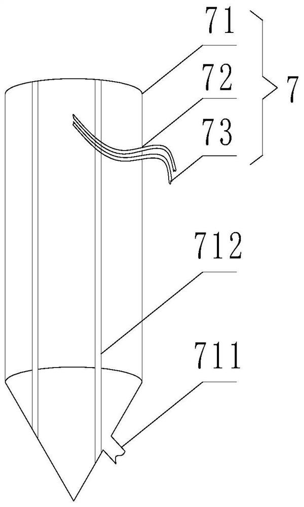
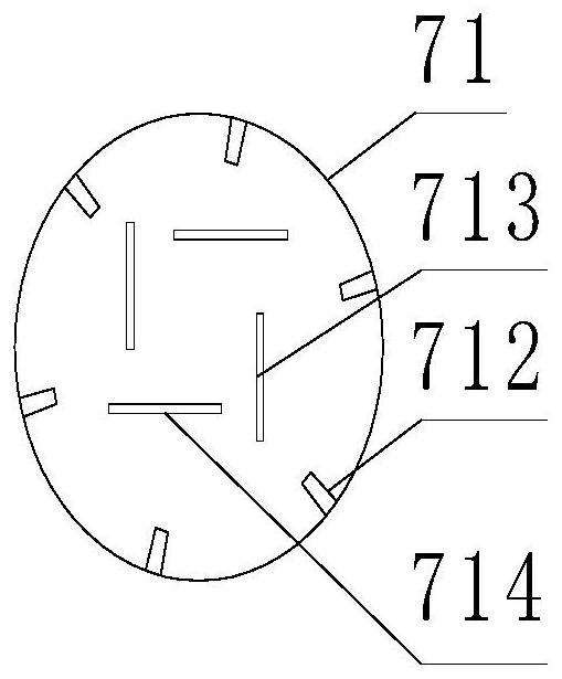
[0028] Such as figure 1 , figure 2 and image 3 As shown, the application provides a carbon dioxide and oxygen gas mixing device 7, comprising a cylindrical mixing barrel 71, a carbon dioxide high-pressure intake pipe 72 and an oxygen high-pressure intake pipe 73; into the upper end of the cylindrical mixing barrel 71, of course the carbon dioxide high-pressure inlet pipe 72 and the oxygen high-pressure inlet pipe 73 can be separated from the inwall of the cylindrical mixing barrel 71, and only the carbon dioxide high-pressure inlet p...


PUM


Abstract

This application relates to the field of combustion and environmental protection, in particular to a carbon dioxide and oxygen gas mixing device and a mixed gas combustion-supporting pollution gas zero-emission system. Since the gas participating in the combustion-supporting gas is a mixture of oxygen and carbon dioxide, oxygen participates in combustion to generate carbon dioxide when fully burned. The content of carbon dioxide in the tail gas is quite high, which can reach more than 95%, so it greatly reduces the difficulty of recovering carbon dioxide, reduces the cost of recovering carbon dioxide, and also greatly reduces the emission of carbon dioxide and reduces the impact on the atmosphere. At the same time, because the gas involved in the combustion is a mixture of oxygen and carbon dioxide, it also avoids a large amount of nitrogen from participating in the combustion, thereby avoiding the emission of nitrogen oxides, thereby reducing the pollution to the atmosphere. It also alleviates the generation of smog and improves the thermal efficiency of combustion.

Description

technical field [0001] The application relates to the fields of combustion and environmental protection, and in particular to a carbon dioxide and oxygen mixing device and a mixed gas combustion-supporting pollution gas zero-emission system. Background technique [0002] Due to the rapid development of urbanization and modern industry, the large-scale use of fuels such as coal, oil, and natural gas by humans, coupled with large-scale fires and the destruction of green vegetation, have led to an increase in the concentration of pollutants in the atmospheric environment year by year, causing Serious environmental pollution, severe climate change and extreme weather have been brought about, so reducing polluting gas emissions is a top priority. [0003] At present, the measures to reduce the emission of polluting gases are generally to increase the tail gas treatment system to treat the dust and harmful gases in the tail gas, and then discharge the treated tail gas into the atm...

Claims


Application Information

Patent Timeline
Patent Type & Authority Patents(China)
IPC IPC(8): B01F5/00F23J15/00F23J15/02F23L7/00
CPCF23J15/006F23J15/02F23L7/00F23J2215/20F23J2215/10F23J2215/40F23L2900/07007F23L2900/07001B01F25/102B01F2101/501Y02E20/32Y02E20/34
Inventor 高振发高鹏高强
Owner 张家口新金石科技发展有限公司
Why Eureka
Try Eureka