Pulse laser emission circuit

A technology of transmitting circuit and pulsed laser, applied in the field of laser measurement, can solve the problems of large ripple, unadjustable high voltage, unstable voltage, etc., and achieve the effects of small parasitic parameters, strong stability, and reduced power loss

Inactive Publication Date: 2017-12-05
NANJING UNIV OF SCI & TECH
View PDF5 Cites 10 Cited by
  • Summary
  • Abstract
  • Description
  • Claims
  • Application Information

AI Technical Summary

Problems solved by technology

Common high-voltage generating circuits are realized by using DC-DC boost circuit and charging and discharging of large inductance. The voltage is unstable, the high voltage is not adjustable, and the ripple is large.

Method used


Image

  • Pulse laser emission circuit
  • Pulse laser emission circuit
  • Pulse laser emission circuit

Examples


Embodiment Construction

[0016] It is easy to understand that, according to the technical solution of the present invention, those skilled in the art can imagine various implementations of the pulsed laser emitting circuit of the present invention without changing the essence of the present invention. Therefore, the following specific embodiments and drawings are only exemplary descriptions of the technical solution of the present invention, and should not be regarded as the entirety of the present invention or as a limitation or limitation on the technical solution of the present invention.

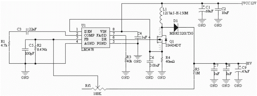
[0017] combine figure 1 , the high voltage generating circuit of the laser diode SPLPL90_3 includes a boost controller U1LM3478, a first resistor R1, a third capacitor C3, a fifth capacitor C5, a second resistor R2, a sliding rheostat Rf1, a third resistor R3, a fourth capacitor C4, a Six capacitors C6, fourth resistor R4, switch MOS chip SI4434DYQ1, first inductor L1, first diode D1, fifth resistor R5, first ca...


PUM


Abstract

The invention provides a pulse laser emission circuit. The pulse laser emission circuit comprises a high voltage generation circuit and a laser emission driving circuit, wherein a high voltage is provided for the driving circuit through the high voltage generation circuit, an laser is emitted by the driving circuit; on and off of an MOS tube are controlled by a booster controller through generating a switch signal, at the instant start moment of the MOS tube, an energy storage inductor is charged through a power source voltage, electric energy is stored in a capacitor through a loop formed by a first diode, after an MOS chip is disconnected, reverse cut-off of the diode is carried out, an output capacitor discharges to a load, and the 160V high voltage is generated; current amplification of the driving signal is carried out through a current amplification chip, the signal after amplification is inputted to a grid of the switch MOS chip, within the turn-off time of the switch MOS tube, a high voltage source provided by the high voltage generation circuit is utilized to charge the energy storage capacitor, the energy storage capacitor realizes instant discharge at the loop of the laser diode within the start time of the switch MOS tube, a heavy current is generated, and the high repetition frequency narrow pulse laser can be emitted.

Description

technical field [0001] The invention belongs to the technical field of laser measurement, and in particular relates to a pulsed laser emitting circuit. Background technique [0002] The laser ranging system uses a laser as a light source, and the transmitter emits a laser with a certain frequency and pulse width. The wave signal is received by the photoelectric detector, and then amplified and shaped by the subsequent circuit to identify the moment of receiving the echo, calculate the laser flight time t, and calculate the distance according to the flight time to complete the distance measurement. Compared with other ranging methods, the laser ranging system has the characteristics of cheap price, simple structure, strong reliability, strong anti-interference ability, wide application range, and good concealment, especially in the military field. It has an unshakable application status. [0003] The pulse laser emission circuit mainly includes the high-voltage generation ci...

Claims


Application Information

Patent Timeline
Patent Type & Authority Applications(China)
IPC IPC(8): G01S7/484H02M3/07
CPCG01S7/484H02M3/07H02M1/0012
Inventor 钱惟贤李之秀顾国华陈钱杨锦清孟思岐蔡贵霞钱烨高青松
Owner NANJING UNIV OF SCI & TECH
Why Eureka
Try Eureka