Energy-saving efficient continuous type plastic garbage thermal cracking refining equipment

A plastic waste and pyrolysis technology, which is applied in the preparation of liquid hydrocarbon mixtures, hydrocarbon oil treatment, petroleum industry, etc., can solve the problems of uneven heating of materials, incomplete utilization of heat energy, poor quality of oil products, etc., and shorten the production cycle , Improve thermal cracking efficiency and improve quality

Pending Publication Date: 2017-12-08
GUANGXI BOSSCO ENVIRONMENTAL PROTECTION TECH
View PDF5 Cites 7 Cited by
  • Summary
  • Abstract
  • Description
  • Claims
  • Application Information

AI Technical Summary

Problems solved by technology

Intermittent pyrolysis oil refining technology is to fill the heatable cracking furnace with plastic waste to pyrolyze and gasify the plastic waste. Usually, it cannot feed continuously, and can only process one pot of plastic waste before proceeding to the next pot, which is less efficient. , long production cycle and high energy consumption; although continuous thermal cracking refinery equipment can realize continuous feeding, continuous slagging and continuous thermal cracking gasification of plastic waste, there are uneven heating of materials and incomplete utilization of heat energy, which leads to easy Sticky wall causes carbon deposition, easy to block channels, low oil production rate, poor oil quality and other defects
The defects of these refining equipment are the important reasons that restrict the industrial application of plastic waste pyrolysis refining technology.

Method used


Image

  • Energy-saving efficient continuous type plastic garbage thermal cracking refining equipment
  • Energy-saving efficient continuous type plastic garbage thermal cracking refining equipment
  • Energy-saving efficient continuous type plastic garbage thermal cracking refining equipment

Examples


Embodiment Construction

[0023] The technical solutions of the present invention will be further described below in conjunction with the accompanying drawings and specific embodiments. In order to make the drawings concise, only parts related to the present invention are schematically shown in the drawings, and only one of the components having the same structure or function is schematically shown in the drawings.

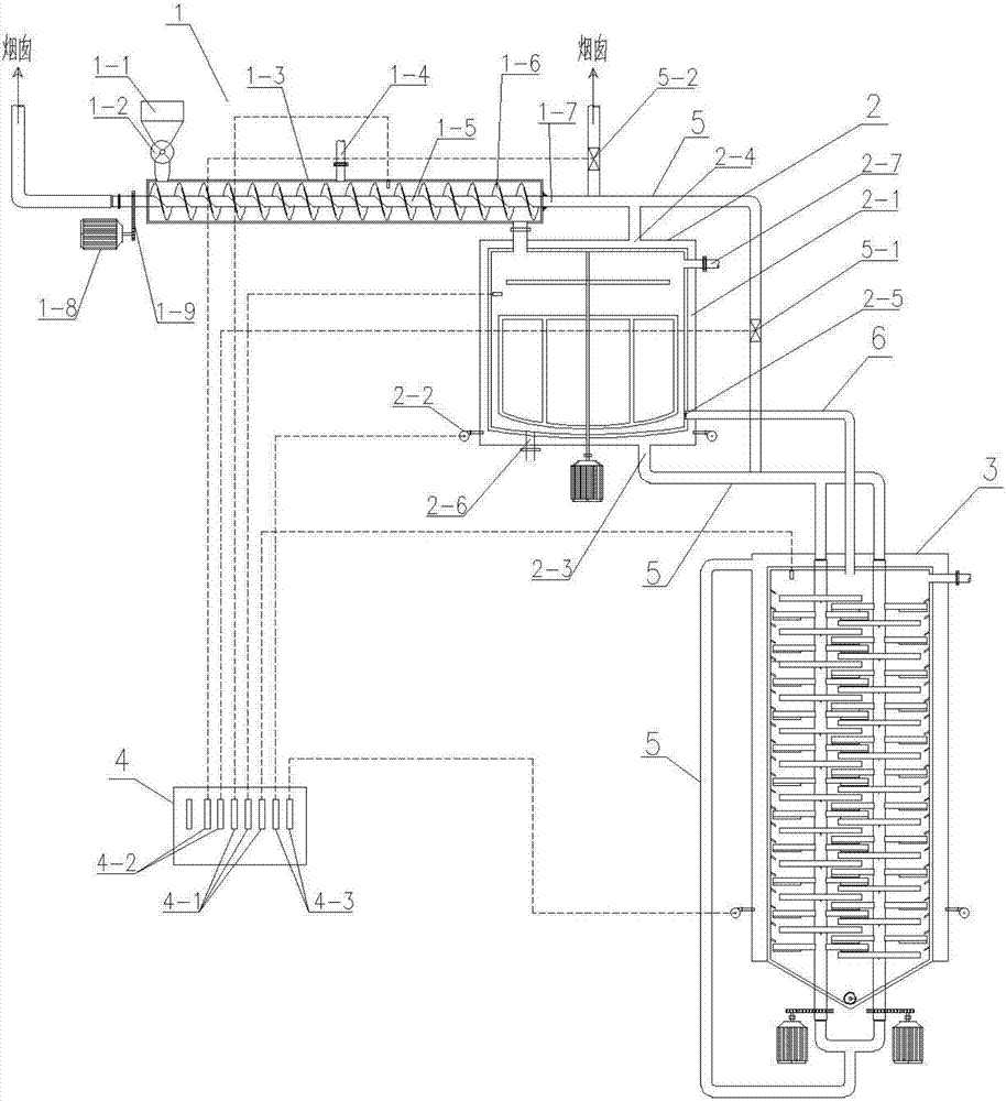
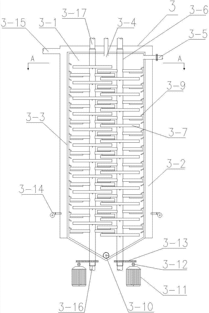
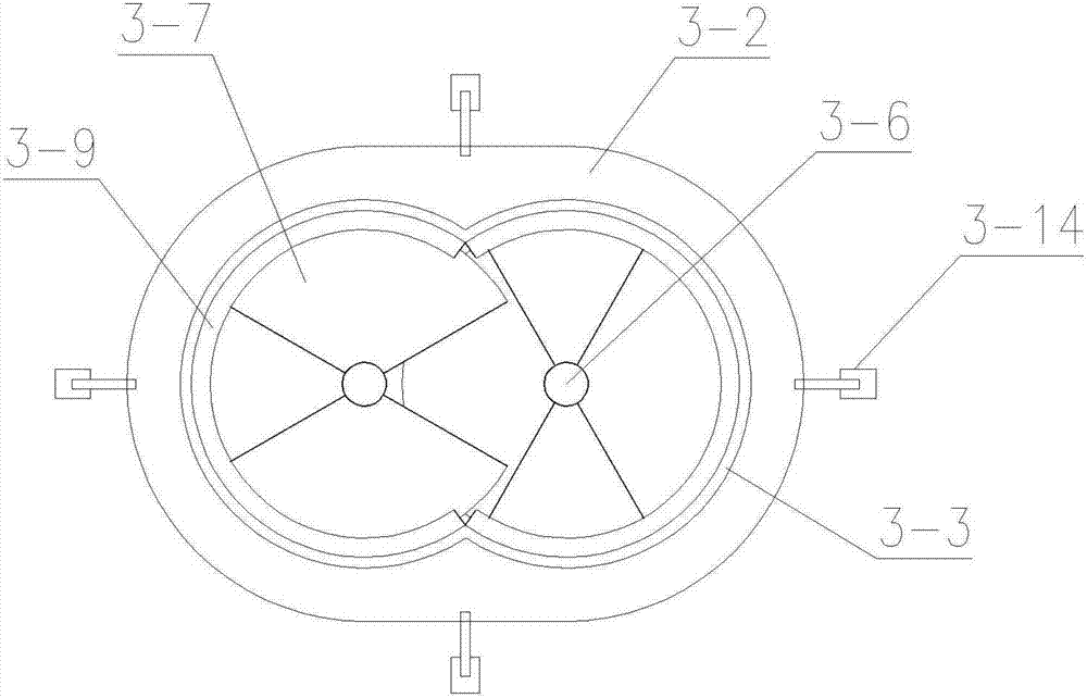
[0024] Such as figure 1 — Figure 4 As shown, the energy-saving and high-efficiency continuous plastic waste pyrolysis refinery equipment of the present invention includes a feed system 1, a liquefaction system, a cracking system (i.e. a cracking furnace 3) and an automatic control system; the liquefaction system includes a liquefier 2 and a liquefaction combustion chamber 2- 1. The liquefaction combustion chamber 2-1 is arranged on the periphery of the liquefier 2, and is supplied with heat by the burner 2-2 and / or the tail gas of the pyrolysis combustion chamber 3-2, and provides heat e...


PUM

PropertyMeasurementUnit
thicknessaaaaaaaaaa

Abstract

The invention discloses energy-saving efficient continuous type plastic garbage thermal cracking refining equipment which comprises a supply system, a liquefaction system and a cracking system; the liquefaction system comprises a liquefaction device and a liquefaction combustion chamber; the liquefaction combustion chamber is arranged at the periphery of the liquefaction device; the cracking system comprises a cracking chamber and a cracking combustion chamber; the cracking combustion chamber is arranged at the periphery of the cracking chamber; the cracking chamber is internally provided with a hollow rotary shaft and a hollow blade; the supply system comprises a screw conveyer; the screw conveyer is provided with a feeding hollow rotary shaft and a hollow spiral blade; the cracking combustion chamber is communicated with the hollow rotary shaft; the hollow rotary shaft is communicated with the liquefaction combustion chamber and the feeding hollow rotary shaft through a flue gas pipeline; the liquefaction combustion chamber is communicated with the feeding hollow rotary shaft; and the exhaust end of the feeding hollow rotary shaft is connected with a chimney. The energy-saving efficient continuous type plastic garbage thermal cracking refining equipment provided by the invention has the advantages of continuous feeding of plastic garbage, good mass and heat transfer effect, rapid thermal cracking speed, high efficiency, energy conservation and the like, can realize continuous production, avoids that plastics coke in a furnace to influence the heat transfer effect and improves the quality of a finished oil product at the same time.

Description

technical field [0001] The invention relates to the technical field of environmental protection equipment, in particular to an energy-saving and high-efficiency continuous thermal cracking oil refining equipment for plastic waste. Background technique [0002] With the progress of the times, people's living standards have been greatly improved, and plastic products have become indispensable consumables in daily life. my country is one of the world's top ten producers and consumers of plastic products. Most of the plastic products have a short service life and are in high demand. They are often discarded after use, causing "white pollution" and endangering the environment. At present, my country's plastic waste disposal methods are mainly landfill and incineration. The landfill method is to bury all the garbage in the ground together. On the one hand, the landfill site needs a lot of land, which wastes land resources. On the other hand, plastic waste is not easy to decompose...

Claims


Application Information

Patent Timeline
Patent Type & Authority Applications(China)
IPC IPC(8): C10G1/00
CPCC10G1/00C10G1/008C10G2300/1003
Inventor 陈国宁林宏飞陆立海熊文标容贤健王爱詹馥蔓杨长钫
Owner GUANGXI BOSSCO ENVIRONMENTAL PROTECTION TECH
Why Eureka
Try Eureka