
Heating furnace tube used for heating gas liquid mixture and/or air-liquid-solid mixture

A gas-liquid mixture and mixture technology, applied in lighting and heating equipment, fixed tubular conduit assemblies, furnaces, etc., can solve the problems of ineffective and effective tubular heating furnaces, tube wall erosion, easy to cause fire, etc., to reduce Consumables costs and labor maintenance costs, production process safety, and the effect of avoiding side wall effects

Inactive Publication Date: 2018-01-05
CATECH TECH
View PDF8 Cites 5 Cited by
  • Summary
  • Abstract
  • Description
  • Claims
  • Application Information

AI Technical Summary

Problems solved by technology

[0003] If the flow rate of heavy oil, oil-coal mixture and other fluids with high viscosity is too low, the flow state will be in the state of laminar flow and laminar turbulent transition, and phenomena such as wall hanging and deposition are prone to occur. If the temperature is too high, it is easy to cause erosion of the pipe wall, leakage and other problems at the joints of the heat exchange pipes, and it is easy to cause accidents such as fire.
The furnace tubes of conventional tube furnaces commonly used in the prior art are divided into a straight tube section and an elbow section. The straight tube section is connected by a 180° elbow. When the fluid flows through the elbow, due to centrifugal movement, the inner and outer sides of the elbow are distorted. The flow velocity is uneven, the outer velocity is fast and the pipe wall is eroded seriously, the inner flow velocity is slow and easy to deposit, and the deposition intensifies the erosion of the fluid on the outer fluid to the pipe wall
Seriously affect the operation cycle of the furnace, and even the production cycle of the device
In order to improve the heat exchange efficiency of the furnace tube, the burner should be as close as possible to the furnace tube, so the burner is arranged along the furnace wall, which brings about a problem: whether the furnace tube is vertical or horizontal, the furnace tube is heated on one side , the fluid in the tube is heated unevenly, and the gasification state is uneven, which may form air resistance and hinder the normal operation of the heating furnace
[0004] In the fields of oil refining, chemical industry and coal chemical industry, it is necessary to heat the mixture of coal and hydrogen. At present, there is still no practical and effective tubular heating furnace for the co-heating of gas-liquid mixture or gas-liquid-solid three-phase mixture. The current tubular heating furnace cannot simultaneously Long-term use does not need to replace the furnace tube, uniform heating, and the advantages of overcoming air resistance

Method used


Image

  • Heating furnace tube used for heating gas liquid mixture and/or air-liquid-solid mixture
  • Heating furnace tube used for heating gas liquid mixture and/or air-liquid-solid mixture
  • Heating furnace tube used for heating gas liquid mixture and/or air-liquid-solid mixture

Examples


Embodiment 1

[0028] Embodiment 1, a kind of tubular heating furnace for heating residual oil, coal powder and hydrogen mixture

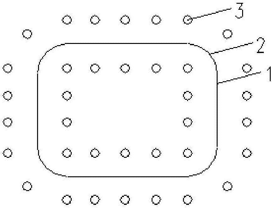
[0029] The tubular heating furnace for heating residue oil, pulverized coal and hydrogen mixture in this embodiment includes a spiral furnace tube and a burner 3; the spiral furnace tube is set upright; the burner is arranged on the spiral furnace tube The inner and outer sides of the spiral circumference of the furnace tube;

[0030] The material to be heated in the tube is a mixture of residual oil, coal powder and hydrogen, the Reynolds coefficient is 2000, and the volume percentage of gas is 75vol%.

[0031] Such as figure 1 , figure 2 and image 3 As shown, the furnace tube installed in the furnace is a rectangular spiral, and the top view is a rounded rectangle, including a straight pipe section 1 and a curved pipe section 2. The inner diameter of the straight pipe section 1 is 50mm, and the length has two specifications, respectively 2500mm and 2000mm ...

Embodiment 2

[0034] Embodiment 2, a kind of tubular heating furnace for heating residual oil and hydrogen mixture

[0035] The tubular heating furnace for heating residue oil and hydrogen mixture in this embodiment includes a spiral furnace tube and a burner 3; the spiral furnace tube is set upright; the burner is arranged on the spiral furnace tube The inner and outer sides of the helical circle; the material to be heated in the tube is a mixture of residual oil and hydrogen, the Reynolds coefficient is 8500, and the volume percentage of gas is 80vol%.

[0036] Such as Figure 4 and Figure 5 As shown, the furnace tube arranged in the furnace is in the shape of a concentric spiral, circular in top view, the inner diameter of the furnace tube is 500 mm, the radius of curvature of the spiral furnace tube is 1500 mm, and the burner 3 is arranged in a linear shape The inner and outer sides of the spiral circle are distributed around the furnace tube on each side. The combustion head of the ...


PUM


Abstract

The invention discloses a heating furnace tube used for heating a gas liquid mixture and / or an air-liquid-solid mixture. The heating furnace tube used for heating the gas liquid mixture and / or the air-liquid-solid mixture comprises a spiral furnace tube and burners, and the spiral furnace tube is vertically arranged. The burners are arranged on the inner side and the outer side of the spiral periphery of the spiral furnace tube. The Reynolds coefficient of the gas-liquid mixture and / or the gas-liquid-solid mixture is 2000-8500. The volume percentage of gas in the gas-liquid mixture and / or thegas-liquid-solid mixture is 75-80 vol%. According to the heating furnace tube used for heating the gas liquid mixture and / or the air-liquid-solid mixture, the spiral furnace tube is in an upright spiral shape, the problem of air resistance is completely overcome, meanwhile, solid deposition is also overcome, the side wall effect is avoided, it is ensured that flow form of a fluid is stable, and especially, the heating furnace tube is suitable for heating mediums containing gas such as the gas-liquid mixture and the gas-liquid-solid mixture.

Description

technical field [0001] The invention relates to the fields of petrochemical industry and coal chemical industry, in particular to a heating furnace tube for heating gas-liquid mixture and / or gas-liquid-solid mixture. Background technique [0002] Heating furnace is a kind of heating equipment widely used in petroleum, chemical industry, metallurgy, electric power and natural gas industries. Its function is to use oil or gas as fuel to heat oil, oil-coal slurry, gas and other media to meet downstream Equipment temperature requirements for process streams. In the petrochemical industry, tubular heating furnaces have been widely used as a heating means to provide heat energy for petrochemical production. Tube heating furnace generally consists of five parts: radiation chamber, convection chamber, waste heat recovery system, burner and ventilation system. Furnace tubes are installed in the radiation chamber and the convection chamber. The furnace tube is an important component...

Claims


Application Information

Patent Timeline
Patent Type & Authority Applications(China)
IPC IPC(8): F27B17/00F27D1/00F28D7/02
Inventor 李苏安邓清宇王坤朋
Owner CATECH TECH
Learn More