Thermal field emission cathode and preparation method thereof, and vacuum electronic device using same

A technology for emitting cathodes and cathode components, which is used in the manufacture of thermionic cathodes, solid thermionic cathodes of discharge tubes, electrical components, etc. problem, to achieve the effect of high emission current density, high emission current density, and improved emission capability

Active Publication Date: 2018-01-09
INST OF ELECTRONICS CHINESE ACAD OF SCI
View PDF6 Cites 6 Cited by
  • Summary
  • Abstract
  • Description
  • Claims
  • Application Information

AI Technical Summary

Problems solved by technology

The field emission cathode of the existing field emission cathode mainly depends on the field enhancement effect brought by the shape and size of the micro-tip, and also depends on the grid and grid voltage applied to the micro-tip at a few microns. Due to the fact that the heating factor was not considered at the beginning of the design of the emitting cathode, and there are defects such as extremely high requirements on the environmental vacuum and poor anti-sparking ability, it is impossible to take advantage of the benefits of increasing the emission capability brought by heating

Method used


Image

  • Thermal field emission cathode and preparation method thereof, and vacuum electronic device using same
  • Thermal field emission cathode and preparation method thereof, and vacuum electronic device using same
  • Thermal field emission cathode and preparation method thereof, and vacuum electronic device using same

Examples


preparation example Construction

[0034]The present invention also proposes a method for preparing a thermal field emission cathode, which includes the following steps: polishing the emitting end surface of the tungsten-copper body; forming a microtip array with pores inside on the emitting end surface of the tungsten-copper body by laser ablation; Remove copper from the tungsten copper body forming the microtip array to obtain a tungsten sponge, so that the pores inside the tungsten sponge are connected with the pores inside the microtip array to obtain a tungsten sponge with a microtip array; brazing or laser welding The tungsten sponge body and the molybdenum cylinder with the microtip array form the cathode assembly; the active material impregnates the cathode assembly at high temperature to complete the preparation method of the thermal field emission cathode.

[0035] Compared with the preparation of traditional field emission cathodes, the preparation method of the present invention does not require expe...

Embodiment 1

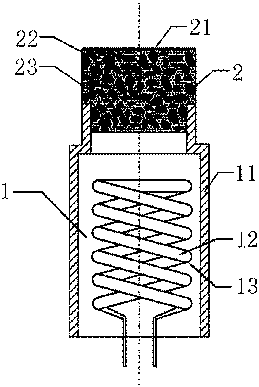
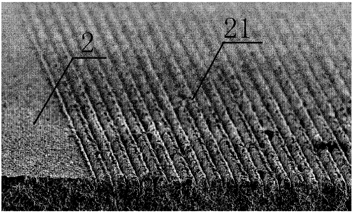
[0065] This embodiment proposes a thermal field emission cathode and a preparation method thereof. The thermal field emission cathode is: a molybdenum cylinder and a tungsten sponge fixed on its upper surface, wherein: the upper surface of the tungsten sponge has a microtip array; the tungsten sponge The pores inside the body and the microtip array form connected pores; the connected pores are filled with active substances.

[0066] The preparation method is specifically:

[0067] Step 1. Select a tungsten copper body that meets the requirements, process and polish it. Specifically, according to the requirements of the cathode drawing, the size of the polishing removal (generally 0.1-0.3mm) is reserved, and the tungsten copper body is processed; then, the surface of the tungsten copper body that is about to be used as the emitter is polished; under normal circumstances, The size of the tungsten-copper body used for melting is relatively small. In order to facilitate processing ...


PUM

PropertyMeasurementUnit
sizeaaaaaaaaaa
diameteraaaaaaaaaa

Abstract

The invention discloses a thermal field emission cathode and a preparation method thereof, and a vacuum electronic device using same. The thermal field emission cathode comprises a molybdenum tube anda tungsten sponge body fixed on the molybdenum tube, wherein the upper surface of the tungsten sponge body has a microtip array, the microtip array is internally provided with pores, pores in the tungsten sponge body and pores in the microtip array form communicated pores, and the communicated pores are internally filled with an active substance. The microtip array is formed on the surface of thetungsten sponge body, the communicated pores from the tungsten sponge body directly to the pores in the microtip array are formed, and the communicated pores are filled with the active substance, sothat the active substance can reach the top of the microtip array under the action of thermal diffusion, thereby providing a condition for realization of low work function emission. Compared with traditional thermal emission cathode, the thermal field emission cathode is greatly lowered in working temperature and power consumption. Compared with traditional field emission cathode, the thermal field emission cathode has higher current emission density and stronger anti-ignition capability.

Description

technical field [0001] The invention belongs to the field of electric vacuum device manufacturing, and more specifically relates to a thermal field emission cathode, a preparation method thereof, and a vacuum electronic device using the same. Background technique [0002] In the field of electric vacuum device manufacturing technology, a large number of cathodes currently used are membrane-impregnated diffusion cathodes, also known as M-type cathodes. It is to store the active emission material (barium aluminate) into the pores of the porous tungsten sponge (cathode substrate) through melting and impregnation, and then deposit a layer of noble metal or alloy film on the surface of the cathode to reduce the electron work function. The operating temperature of this type of cathode is 900-1150°C, which belongs to the traditional hot cathode, and has problems such as working at high temperature, high power consumption, and inability to start instantly. Such as figure 1 As show...

Claims


Application Information

Patent Timeline
Patent Type & Authority Applications(China)
IPC IPC(8): H01J1/142H01J1/144H01J1/20H01J9/04
Inventor 阴生毅卢志鹏张永清张兆传任峰
Owner INST OF ELECTRONICS CHINESE ACAD OF SCI
Why Eureka
Try Eureka