Heat engine-hydrogen reaction bed combined circulating system

A circulating system and reaction bed technology, applied in mechanical equipment, steam engine installations, machines/engines, etc., can solve problems such as low utilization rate of hydrogen energy

Active Publication Date: 2018-01-19
SHANGHAI KELAIPU ENERGY TECH CO LTD
View PDF3 Cites 22 Cited by
  • Summary
  • Abstract
  • Description
  • Claims
  • Application Information

AI Technical Summary

Problems solved by technology

The hydrogen energy utilization rate of the hydrogen reaction bed in the prior art is low, which cannot meet the needs of hydrogen energy vehicles and other power equipment

Method used


Image

  • Heat engine-hydrogen reaction bed combined circulating system
  • Heat engine-hydrogen reaction bed combined circulating system
  • Heat engine-hydrogen reaction bed combined circulating system

Examples


Embodiment 1

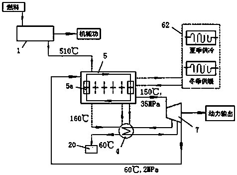
[0040] Heat engine-hydrogen reaction bed combined cycle system of the present invention such as figure 1 As shown, it includes a heat engine 1, a hydrogen compression unit 5, a building energy supply system 62, an intermediate reheater 4 and an expander 7, and the heat engine is a gas turbine. The hydrogen compression unit includes 6 hydrogen reaction beds. The 6 hydrogen reaction beds are equipped with internal heat exchange pipelines to perform hydrogen desorption and hydrogen absorption alternately. The 6 hydrogen reaction beds are connected to the building energy supply system. Such as Figure 5 As shown, the intermediate reheater is a shell-and-tube heat exchanger, which is respectively provided with a heat exchange tube 15, a hydrogen inlet 13, a hydrogen outlet 16, a flue gas inlet 17, and a flue gas outlet 14, the flue gas goes through the shell side, and the hydrogen gas goes through the pipe Procedure. Such as Figure 6 As shown, the expander is a three-stage expa...

Embodiment 2

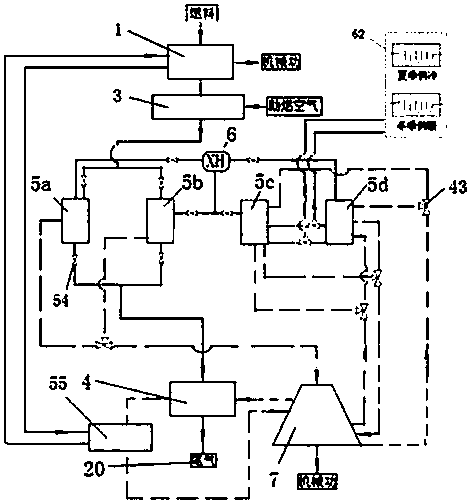
[0053] Another embodiment of the present invention is as figure 2 As shown, it includes a heat engine 1 , a hydrogen compression unit, a combustion chamber 3 , an intermediate reheater 4 , a cylinder cooler 55 , an expander 7 and a metal hydride replacement device 6 . The heat engine is a piston engine, and the cylinder cooler is connected to the heat engine cycle, and the heat from the cooling cylinder heats the circulating hydrogen drawn from the expander. The hydrogen compression unit is equipped with two sets of hydrogen reaction beds, each with two hydrogen reaction beds, namely No. 1 hydrogen reaction bed 5a, No. 2 hydrogen reaction bed 5b, No. 3 hydrogen reaction bed 5c and No. 4 hydrogen reaction bed 5d. The hydrogen reaction beds are arranged side by side. The flue gas inlet and outlet of No. 1 hydrogen reaction bed 5 a and No. 2 hydrogen reaction bed 5 b are provided with valves 54 . The two hydrogen reaction beds in each group alternately perform hydrogen absorpt...

Embodiment 3

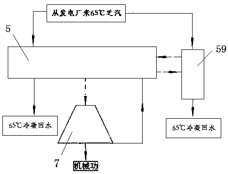
[0058] Another embodiment of the present invention is as image 3 As shown, it includes a hydrogen compression unit 5, an expander 7, an absorption refrigeration device 59, a 65°C exhaust steam pipeline from a power plant and a 65°C condensation return water pipeline. The 65°C exhaust steam pipeline from the power plant is connected to the 65°C condensate return water line through the hydrogen compression unit and absorption refrigeration equipment to return to the power plant. The hydrogen outlet of the hydrogen compression unit is connected to the inlet of the expander, and the outlet of the expander is connected to the hydrogen compression unit. The hydrogen reaction bed of the hydrogen compression unit performs hydrogen desorption and hydrogen absorption alternately, and the hydrogen compression unit is connected to the absorption refrigeration equipment 59 in a cycle. Such as Figure 8 As shown, the hydrogen reaction bed is a casing structure, including a hydrogen circu...


PUM


Abstract

The invention relates to a heat engine-hydrogen reaction bed combined circulating system comprising a heat engine, a hydrogen compression unit, an intermediate reheater and an expansion machine. The hydrogen compression unit is provided with at least one set of hydrogen reaction beds, each set comprises the at least two hydrogen reaction beds, and the hydrogen reaction beds mutually communicate. The expansion machine adopts multiple stages, and a thermal medium outlet of the heat engine is connected to a tail gas discharging opening through the hydrogen reaction beds and the intermediate reheater. The hydrogen reaction beds of the hydrogen compression unit are connected to an inlet of the expansion machine, a first-stage outlet and / or a second-stage outlet of the expansion machine are / is connected with the intermediate reheater or the hydrogen compression unit, an outlet of the intermediate reheater or the hydrogen compression unit is connected with a next-stage inlet of the expansionmachine, and the outlets of the expansion machine are connected to the hydrogen reaction beds of the hydrogen compression unit. The heat engine and the hydrogen reaction beds of the hydrogen compression unit are combined, tail gas waste heat after the heat engine does work is fully utilized to heat metal hydride, high-pressure hydrogen is generated to promote the expansion machine to do work, andthus the thermal efficiency is advantageously improved.

Description

technical field [0001] The invention belongs to the technical field of hydrogen energy power equipment, and relates to hydrogen power cycle utilization equipment, in particular to a heat engine-hydrogen reaction bed combined cycle system. Background technique [0002] In the 21st century, the automobile engine industry has developed rapidly, but gasoline engines and diesel engines are still the main types of automobile engines. Both gasoline and diesel are non-renewable resources. In order to alleviate a series of negative effects brought about by the scarcity of petroleum resources, as well as reduce air pollution and vehicle engine exhaust emissions, it is necessary to find alternative fuels for engines, and hydrogen energy is currently the most ideal clean fuel. The new energy economy that replaces the fossil energy economy, or the new energy economy in the post-petroleum era will be "hydrogen energy economy", "low-carbon economy" and its diversification of nuclear energ...

Claims


Application Information

Patent Timeline
IPC IPC(8): F01K27/02F01D15/10
Inventor 贾鹏
Owner SHANGHAI KELAIPU ENERGY TECH CO LTD
Why Eureka
Try Eureka