Absolute photoelectric encoder decoding circuit
A technology of photoelectric code disc and decoding circuit, which is applied in the field of communication, can solve the problems that the decoding circuit and the overall accuracy of the control system are greatly affected, the circuit is not self-adaptive, and the service life is short, so as to achieve a high accuracy rate of fault diagnosis , strong self-adaptive ability and high circuit reliability
- Summary
- Abstract
- Description
- Claims
- Application Information
AI Technical Summary
Problems solved by technology
Method used
Image

Examples
Embodiment Construction
[0017] The present invention will be further described below in conjunction with drawings and embodiments.
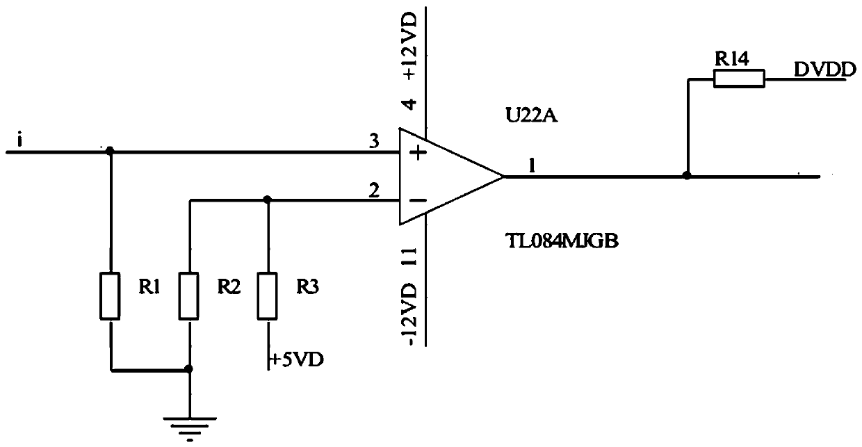
[0018] Such as figure 1 , the coarse code comparison amplifier circuit uses the operational amplifier as a comparator to compare the original signal of the coarse code with its comparison voltage to obtain an output signal. If the comparison voltage of the coarse code is properly selected, it can be well guaranteed to reshape the original trapezoidal wave signal of the coarse code into a square wave signal. The sampling resistor R1 converts the original photocurrent signal of the rough code into a voltage signal, and compares it with the +5V divided voltage on R2 and R3 (that is, the pin 6 voltage). If it is higher than the comparison voltage, the coarse code output voltage u=3.3 v, if it is lower For comparison voltage, the coarse code output is 0V.
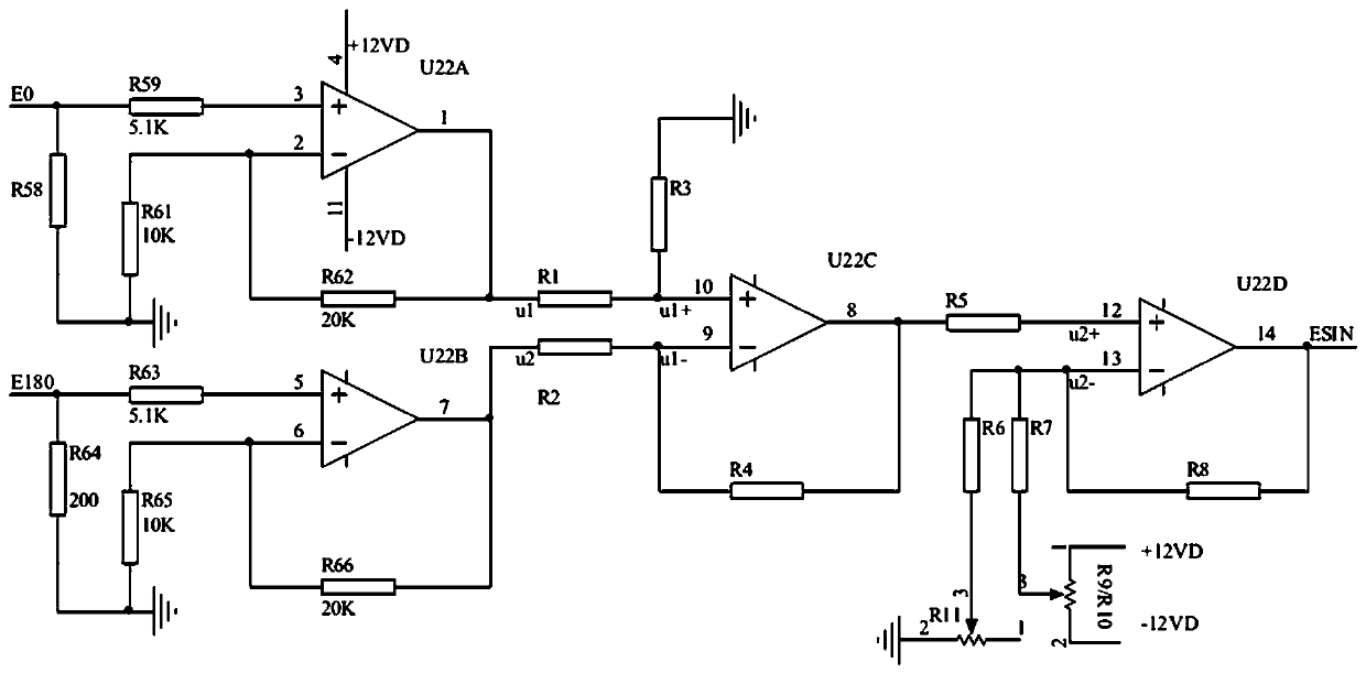
[0019] Such as figure 2 , In the fine code differential amplifier circuit, the four signals of fine code are E0, E9...
PUM
 Abstract
Description
Claims
Application Information
 - R&D
- Intellectual Property
- Life Sciences
- Materials
- Tech Scout
- Unparalleled Data Quality
- Higher Quality Content
- 60% Fewer Hallucinations
Browse by: Latest US Patents, China's latest patents, Technical Efficacy Thesaurus, Application Domain, Technology Topic, Popular Technical Reports.
© 2025 PatSnap. All rights reserved.Legal|Privacy policy|Modern Slavery Act Transparency Statement|Sitemap|About US| Contact US: help@patsnap.com