
High repetition frequency fiber laser based on principle of phase offset device and control method

A fiber laser and high repetition frequency technology, applied in lasers, laser components, instruments, etc., can solve the problems of reducing modulation depth, achieve the effect of reducing threshold, increasing repetition frequency and shortening length

Inactive Publication Date: 2018-01-30
PEKING UNIV
View PDF4 Cites 8 Cited by
  • Summary
  • Abstract
  • Description
  • Claims
  • Application Information

AI Technical Summary

Problems solved by technology

However, in order to reduce the difficulty of self-starting, the above works still use a coupler with a large splitting ratio, which reduces the modulation depth at the same time

Method used


Image

  • High repetition frequency fiber laser based on principle of phase offset device and control method
  • High repetition frequency fiber laser based on principle of phase offset device and control method

Examples


Embodiment 1

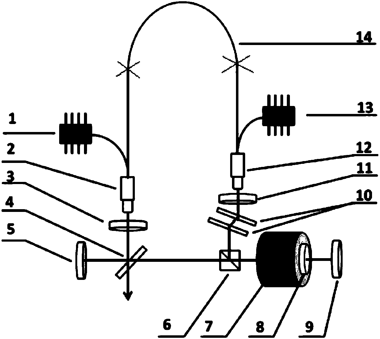
[0030] Such as figure 1 As shown, the high repetition rate fiber laser based on the principle of the phase offset device in this embodiment includes: a first pump source 1, a first wavelength division multiplexing collimator 2, a first half-wave plate 3, a beam splitter Device 4, first mirror 5, polarization beam splitter cube 6, Faraday rotator 7, birefringent crystal 8, second mirror 9, grating pair 10, second half-wave plate 11, second wavelength division complex With collimator 12, the second pumping source 13 and polarization maintaining fiber 14; Wherein, the first pumping source 1 is connected to the tail of the first wavelength division multiplexing collimator 2, and the second pumping source 13 is connected to the first The tail of the two wavelength division multiplexing collimator 12; the tail fiber of the first wavelength division multiplexing collimator 2 and the second wavelength division multiplexing collimator 12 is a gain fiber, connected by a polarization mai...

Embodiment 2

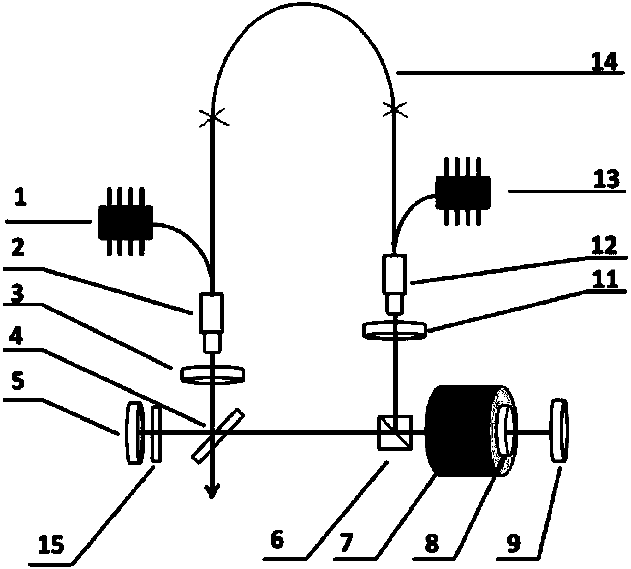
[0033] Such as figure 2 As shown, the high repetition rate fiber laser based on the principle of the phase offset device in this embodiment includes: a first pump source 1, a first wavelength division multiplexing collimator 2, a first half-wave plate 3, a beam splitter Device 4, first mirror 5, polarization beam splitter cube 6, Faraday rotator 7, birefringent crystal 8, second mirror 9, second half-wave plate 11, second wavelength division multiplexing collimator 12. A second pumping source 13, a polarization maintaining fiber 14 and a bandpass filter 15. In this embodiment, a bandwidth control element is used to replace the grating pair, and the bandwidth control element is a filter 15 arranged between the beam splitter and the first reflector to limit the spectrum, and the others are the same as in the first embodiment.


PUM


Abstract

The invention discloses a high repetition frequency fiber laser based on the principle of a phase offset device and a control method. According to the invention, a high repetition frequency fiber laser forms a nonlinear amplifying loop mirror; a mirror and a beam splitter are used to divide a pulse into two lights, and the lights are rotated counterclockwise and clockwise respectively; Faraday rotation and a birefringent crystal form a phase shift unit; the first light and the second light produce phase difference of pi / 2; the first light and the second light are recombined to realize nonlinear phase-shift mode locking; the threshold for mode locking startup is greatly reduced; the repetition frequency is improved; the overall stability and reliability are improved; a fiber wavelength division multiplexing collimator is used to replace a conventional fiber wavelength division multiplexer and a fiber collimator; the Faraday rotating mirror of a thin-film magneto-optic material is used to replace a conventional optical fiber isolator or the free-space isolator of a crystal magneto-optic material, which greatly shortens the length of a fiber in the fiber laser; the laser system is simplified; the coupling power and the efficiency are improved; and the repetition frequency is improved.

Description

technical field [0001] The invention relates to a mode-locked fiber laser, in particular to a high-repetition-frequency fiber laser and a control method based on the principle of a phase offset device. Background technique [0002] Driven by research fields such as spectroscopy, nonlinear optical imaging and others, the demand for ultrafast lasers has been expanding in recent years. Especially in the rapidly growing industrial high-end micro-processing market in recent years, the demand for high-end picosecond and femtosecond lasers continues to grow. However, these fields represented by industry have put forward higher requirements for the stability of ultrafast lasers in different environments, and the stability and reliability of industrial ultrafast lasers, especially seed sources, have not been well established. solve. The use of fiber technology to replace the solid seed source technology itself has many advantages, and the use of full polarization-maintaining fiber ...

Claims


Application Information

Patent Timeline
IPC IPC(8): H01S3/067H01S3/091H01S3/10H01S3/11G02F1/095G02B27/28
Inventor 刘关玉张志刚
Owner PEKING UNIV
Learn More