Picosecond laser machining equipment

A picosecond laser and processing equipment technology, applied in laser welding equipment, metal processing equipment, welding equipment, etc., can solve problems such as difficult to deal with curved contours and low cutting efficiency, and achieve the effect of improving processing quality and processing efficiency

Inactive Publication Date: 2018-03-02
SHENZHEN INSTITUTE OF INFORMATION TECHNOLOGY
View PDF34 Cites 19 Cited by
  • Summary
  • Abstract
  • Description
  • Claims
  • Application Information

AI Technical Summary

Problems solved by technology

[0003] However, as brittle materials suitable for electronic products continue to develop in the direction of thinner, more scratch-resistant, and deeper strengthening layers, existing laser processing equipment can no longer meet the processing requirements for these brittle materials, and it is difficult to handle complex bending profiles , low cutting efficiency

Method used


Image

  • Picosecond laser machining equipment
  • Picosecond laser machining equipment
  • Picosecond laser machining equipment

Examples


Embodiment 1

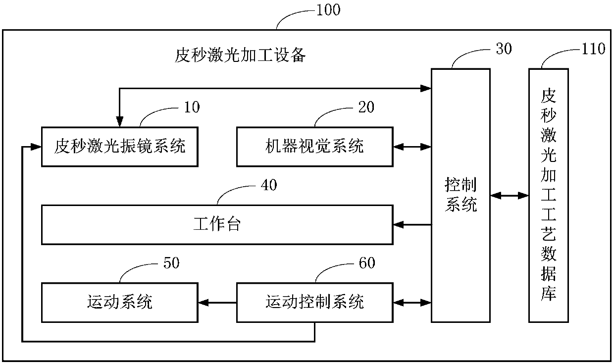
[0038] Such as figure 1 As shown, this embodiment provides a picosecond laser processing equipment 100 , which includes a picosecond laser galvanometer system 10 , a machine vision system 20 , a control system 30 , a workbench 40 , a motion system 50 and a motion control system 60 .

[0039] In one embodiment, the picosecond laser processing equipment also includes a picosecond laser processing technology database stored in the storage device, and the control system calls the data in the picosecond laser processing technology database for the picosecond laser galvanometer system, machine vision system, The working state of the workbench and motion control system is controlled to realize laser precision machining of brittle materials.

[0040] Such as figure 1 As shown, the picosecond laser processing technology database 110 stored in the storage device is exemplarily shown, and the control system 30 can call the data in the picosecond laser processing technology database 110,...

Embodiment 2

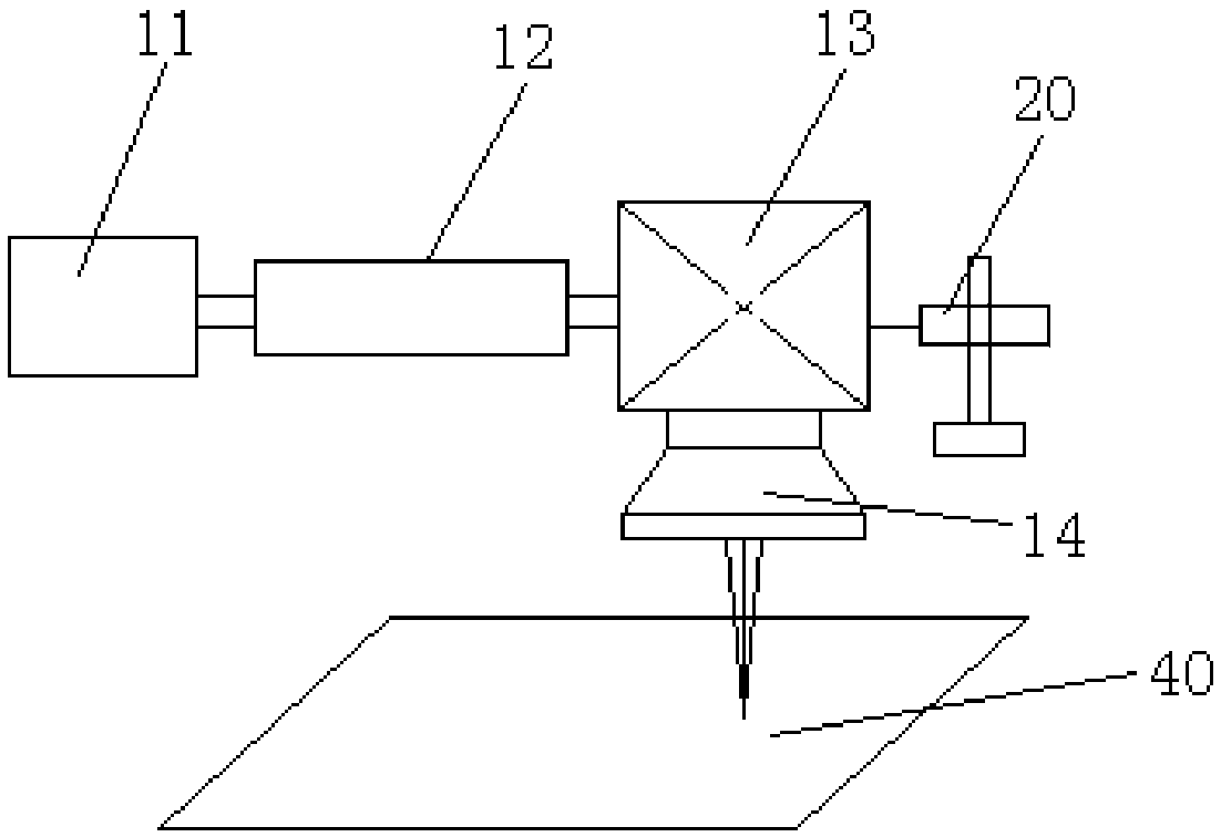
[0068] Such as image 3 As shown, in one embodiment of the present invention, the picosecond laser vibrating mirror system 10 includes a picosecond laser 11, an optical path system 12, a vibrating mirror system 13 and an autofocus system 14, and the optical path system 12 includes at least one mirror (in the figure not shown), the vibrating mirror system 13 includes an X-direction scanning mirror and a Y-direction scanning mirror (not shown in the figure), and the self-focusing system 14 includes at least one focusing lens (not shown in the figure).

[0069] image 3 The relative positional relationship between the systems in the picosecond laser galvanometer system 10 is only exemplarily shown; wherein, the optical path system 12 is arranged on the light exit side of the picosecond laser 11, and the galvanometer system 13 is arranged on the light exit side of the optical path system 12. side, the self-focusing system 14 is set on the light-emitting side of the galvanometer s...

Embodiment 3

[0087] Such as Figure 5 As shown, in one embodiment of the present invention, the optical path system 12 includes a beam expander 121, a first reflector 122, a second reflector 123, a third reflector 124, The fourth reflector 125, the X-direction translation mechanism (not shown in the figure), and the Z-direction lifting mechanism (not shown in the figure).

[0088] Such as Figure 5 As shown, in this embodiment, the beam expander 121 is arranged on the light-emitting side of the picosecond laser 11, and the relative positions of the picosecond laser 11, the beam expander 121, the first reflector 122 and the second reflector 123 are fixed and uniform. Sealed installation, the third reflector 124 is arranged on the X-direction translation mechanism, the fourth reflector 125 is arranged on the Z-direction lifting mechanism, the third reflector 124, the fourth reflector 125, the X-direction translation mechanism and the Z-direction lifting mechanism Arranged in the same seale...


PUM


Abstract

The invention relates to the technical field of laser machining, and provides picosecond laser machining equipment used for machining fragile materials. The picosecond laser machining equipment comprises a picosecond laser galvanometer system, a machine vision system, a control system, a workbench, a motion system and a motion control system; the picosecond laser galvanometer system and the machine vision system are arranged above the workbench; the picosecond laser galvanometer system and the motion system are electrically connected with the motion control system; the motion system is in mechanical connection with the workbench; and the picosecond laser galvanometer system, the machine vision system, the workbench and the motion control system are electrically connected with the control system. Through a picosecond laser machining technology, the picosecond laser precision machining of the fragile materials is realized. Superfine machining on the machining positions of the fragile materials provided with deep-layer strengthening layers can be realized, the machining of a complicated bent outline can be realized, and the machining quality and the machining efficiency are improved effectively.

Description

technical field [0001] Embodiments of the present invention belong to the technical field of laser processing, and in particular relate to picosecond laser processing equipment. Background technique [0002] With the continuous development of laser processing technology, various laser processing equipment emerge in endlessly. It can realize various laser processing functions such as laser cutting, laser marking and laser welding. Laser processing equipment for cutting brittle materials such as sapphire glass cover plates, optical glass, semiconductor packaging chips, sapphire silicon wafer ceramic substrates, etc., can be widely used in the shape cutting of various electronic product cover plates and optical lenses, liquid crystal panels Cutting, fingerprint identification chip cutting, etching and cutting of microelectronic circuit boards, etc., the application prospects are very broad. [0003] However, as brittle materials suitable for electronic products continue to de...

Claims


Application Information

Patent Timeline
Patent Type & Authority Applications(China)
IPC IPC(8): B23K26/38B23K26/402B23K26/70B23K26/08B23K26/046
CPCB23K26/046B23K26/0861B23K26/38B23K26/402B23K26/702B23K26/703
Inventor 肖海兵刘明俊
Owner SHENZHEN INSTITUTE OF INFORMATION TECHNOLOGY
Why Eureka
Try Eureka