
Additive welding method for large-thickness frame metal parts

A technology for metal parts and welding methods, applied in the field of additive welding, can solve the problems of poor coupling of composite welding technology, low penetration rate of laser welding technology, and difficult implementation work, so as to reduce the difficulty of implementation conditions, reduce welding defects, and solve The effect of a high power threshold

Inactive Publication Date: 2018-04-06
NANJING UNIV OF AERONAUTICS & ASTRONAUTICS
View PDF7 Cites 11 Cited by
  • Summary
  • Abstract
  • Description
  • Claims
  • Application Information

AI Technical Summary

Problems solved by technology

In the current common welding technology for large-thickness frame parts, electron beam welding needs to be carried out in a vacuum environment. The actual implementation is difficult, the cost is high, and the cycle is long; multi-layer multi-pass welding has the phenomenon of non-fusion between layers, and there are many welding defects. The quality of the weldment is low and the service life is short; the laser welding technology has low penetration rate, poor bridging performance, and plasma shielding effect; and the hybrid welding technology has poor coupling phenomenon, low flexibility, and is prone to welding defects

Method used


Image

  • Additive welding method for large-thickness frame metal parts
  • Additive welding method for large-thickness frame metal parts
  • Additive welding method for large-thickness frame metal parts

Examples


Embodiment 1

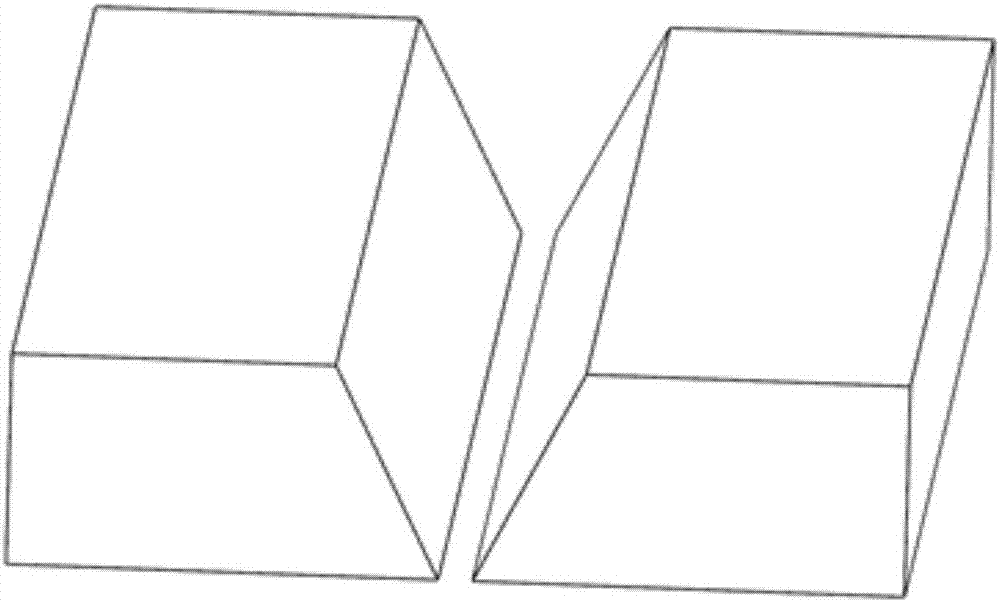
[0032] For the welding of high-performance TC4 titanium alloy parts with a thickness of 140mm, according to assembly requirements, the present invention first prepares a single-sided V-shaped groove on the parts to be welded, the groove angle is 60°, and the blunt edge size is 2-3mm, such as figure 1 As shown, the bevel is prepared by machining. Grind the beveled weldment with sandpaper, then clean it with acetone to remove surface impurities, take it out and dry it, and use the reverse deformation method to clamp the parts to be welded. The solder adopts mechanical ball milling method to prepare TC4 titanium alloy powder, and the particle diameter is 100-150 μm.

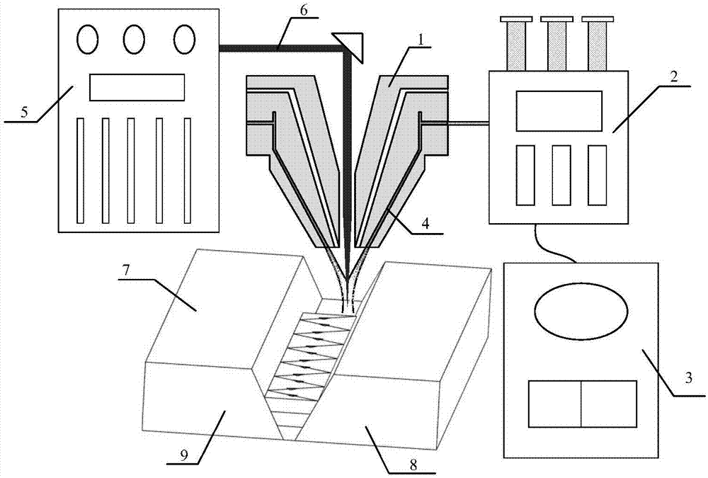
[0033] Conduct laser additive welding experiments, such as figure 2 As shown, the powder feeding head 1 is connected to the powder powder supply box 2, the powder powder supply box 2 is connected to the CNC machine tool 3 on the welding machine, and the powder feeding head transports the alloy powder 4 according t...

Embodiment 2

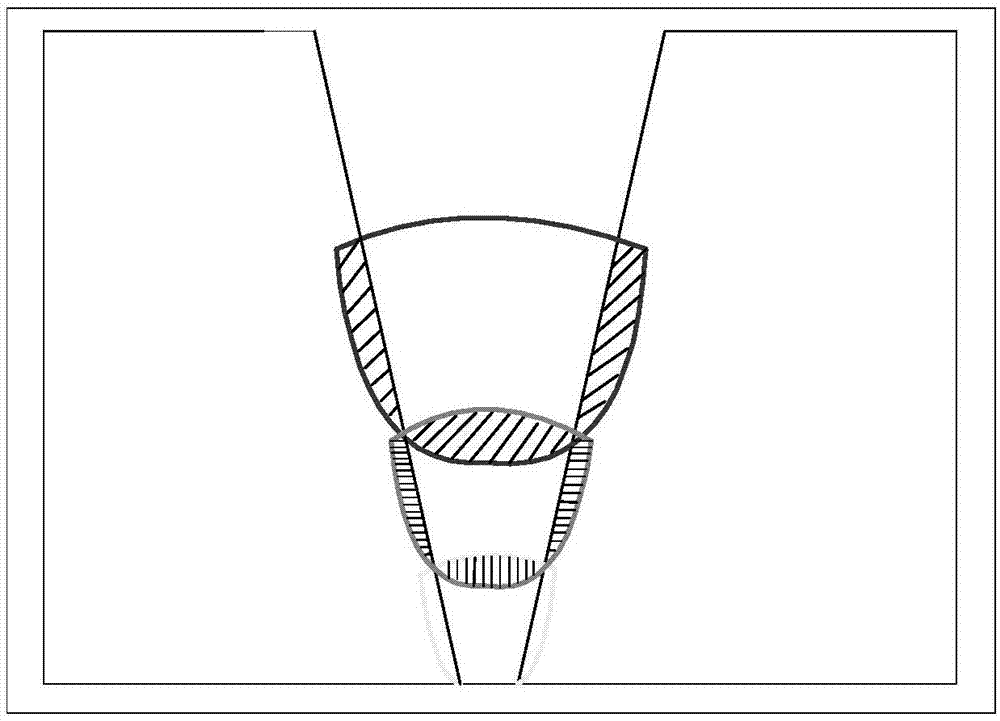
[0036] For the welding of high-performance TC4 titanium alloy parts with a thickness of 140mm, according to assembly requirements, the present invention first prepares a single-sided U-shaped groove on the parts to be welded, the root of the groove is an arc, and the bevel angles on both sides are 3-7° , the blunt edge size is 3-6mm, such as Figure 5 As shown, the bevel is prepared by machining. Grind the beveled weldment with sandpaper, then clean it with acetone to remove surface impurities, take it out and dry it, and use the reverse deformation method to clamp the parts to be welded. The solder is prepared by mechanical ball milling method to prepare TC4 titanium alloy powder, and the particle diameter is 100-150 μm.

[0037] Conduct laser additive welding experiments, such as Image 6 As shown, the powder feeding head 1 is connected to the powder powder supply box 2, the powder powder supply box 2 is connected to the CNC machine tool 3 on the welding machine, and the p...


PUM

PropertyMeasurementUnit
diameteraaaaaaaaaa
thicknessaaaaaaaaaa
angleaaaaaaaaaa

Abstract

The invention discloses an additive welding method for large-thickness frame metal parts, which comprises the following steps: (1) groove shape design and welding preparation: preparing a single-facegroove which is a U-shaped groove or a V-shaped groove, sanding the to-be-welded part with the groove, cleaning the part with acetone to remove surface impurities, taking out and blow-drying the to-be-welded part, and clamping the to-be-welded part by a reversible deformation method, wherein the welding flux is alloy powder by ball milling, and the particle diameter is 100 to 150 microns; (2) laser additive welding experiment: a powder head and a powder supply box are connected in a selected welding device, the powder supply device is connected with a numerical control machine tool on a welding machine tool, according to a preset track, the powder head supplies the alloy powder which is in a coaxial coupling relationship with the laser light output by a laser, the fused surface of the to-be-welded part and the alloy powder form a large multi-layered fused area, and the weld pool Is cooled and solidified to form a stack layer, and the connection between two to-be-welded parts is realized.

Description

Technical field: [0001] The invention relates to an additive welding method for large-thickness frame metal parts, which belongs to the field of additive welding. Background technique: [0002] With the rapid development of the aerospace industry, the welding quality requirements for large-thickness frame parts such as the body frame are getting higher and higher. In the current common welding technology for large-thickness frame parts, electron beam welding needs to be carried out in a vacuum environment. The actual implementation is difficult, the cost is high, and the cycle is long; multi-layer multi-pass welding has the phenomenon of non-fusion between layers, and there are many welding defects. The quality of the weldment is low and the service life is short; the laser welding technology has low penetration rate, poor bridging performance, and plasma shielding effect; and the hybrid welding technology has poor coupling phenomenon, low flexibility, and is prone to weldin...

Claims


Application Information

Patent Timeline
Patent Type & Authority Applications(China)
IPC IPC(8): B23K26/26B23K26/60B23K33/00
CPCB23K26/26B23K26/60B23K33/004
Inventor 占小红齐超琪孟遥周俊杰田德勇
Owner NANJING UNIV OF AERONAUTICS & ASTRONAUTICS
Learn More