Environmental-protection drying device

A drying device, an environment-friendly technology, applied in heating devices, manure drying, drying solid materials, etc., can solve the problems of different particle sizes and different drying degrees, and achieve the effect of strengthening heat preservation, high work efficiency and reducing costs

Inactive Publication Date: 2018-04-13
成都元始信息科技有限公司
View PDF0 Cites 1 Cited by
  • Summary
  • Abstract
  • Description
  • Claims
  • Application Information

AI Technical Summary

Problems solved by technology

[0006] The purpose of the present invention is to provide an environment-friendly drying device in order to solve the technical problem of different drying degrees caused by inconsistent particle sizes of existing drum dryers.

Method used


Image

  • Environmental-protection drying device
  • Environmental-protection drying device
  • Environmental-protection drying device

Examples


Embodiment 1

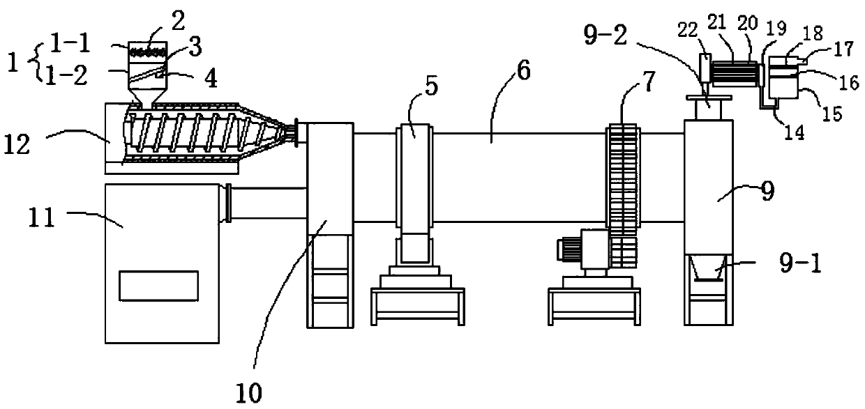
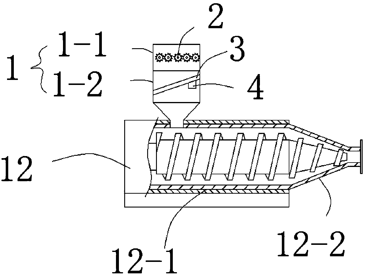
[0027] Such as Figures 1 to 5 As shown, the present embodiment provides an environment-friendly drying device, comprising a feed head 10 and a discharge head 9, a drum 6 is arranged between the feed head 10 and the discharge head 9, and the feed head 10 It is connected with a combustion chamber 11, and it is characterized in that the feed port of the feed head 10 is connected with a composite feed mechanism, the composite feed mechanism includes a conveying chamber 12, and the conveying chamber 12 includes a cylindrical chamber 12 welded into one -1 and conical cavity 12-2, the outlet of conical cavity 12-2 is connected to the feed port of feed head 10, and the cylindrical cavity 12-1 is provided with a compound feed hopper 1, which includes the upper The pre-crushing chamber 1-1 and the vibrating feeding chamber 1-2 connected with the cylindrical chamber 12-1 below, the vibrating screen 3 is arranged in the vibrating feeding chamber 1-2, and the composite vibrating mechanism...

Embodiment 2

[0031] This embodiment is further optimized on the basis of embodiment 1, specifically:

[0032] The drum 6 is provided with a gear drive mechanism 7 which drives the drum 6 to rotate, and the drum 6 is provided with a driven rotation mechanism 5 .

[0033] The composite thermal insulation layer 6-2 includes several layers of glass fiber layers 6-2.1 and several layers of aluminum foil layers 6-2.2, the glass fiber layers 6-2.1 and aluminum foil layers 6-2.2 are stacked alternately, and the adjacent two layers of aluminum foil layers 6-2.2 No Contact.

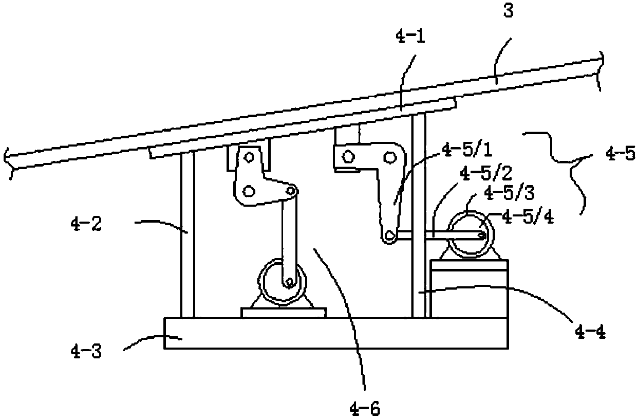
[0034] Described composite vibration mechanism 4 comprises vibrating plate 4-1 and support base plate 4-3, is provided with connecting rod A4-2 and connecting rod B4-4 between vibrating plate 4-1 and supporting base plate 4-3, and supporting base plate 4- 3 is provided with a horizontal vibration mechanism 4-5 for controlling the horizontal vibration of the vibration plate 4-1 and a vertical vibration mechanism 4-6 for control...

Embodiment 3

[0036] This embodiment is further optimized on the basis of embodiment 1 or 2, specifically:

[0037] The horizontal vibration mechanism 4-5 includes a horizontal motor 4-5 / 3, a horizontal connecting rod 4-5 / 2, and one end connected to the horizontal connecting rod 4-5 / 2 and the other end connected to the vibration The horizontal curved plate 4-5 / 1 is movably connected to the bottom side of the middle part of the plate 4-1, the output end of the horizontal motor 4-5 / 3 is provided with a horizontal turntable 4-5 / 4, the horizontal turntable 4-5 / 4 and the horizontal connecting rod 4 -5 / 2 is movably connected, and the connection between the horizontal turntable 4-5 / 4 and the horizontal connecting rod 4-5 / 2 is far away from the center of circle of the horizontal turntable 4-5 / 4.

[0038] A plurality of flaps 13 are arranged inside the drum 6 .


PUM


Abstract

The invention discloses an environment-friendly drying device, which relates to the technical field of drying equipment. The invention includes a feed head and a discharge head, a roller is arranged between the feed head and the discharge head, and the feed head is connected There is a combustion chamber, the feed port of the feed head is connected with a composite feed mechanism, the composite feed mechanism includes a conveying chamber, and the drum includes an inner cylinder and an outer cylinder sleeved outside the inner cylinder, A vacuum insulation cavity is formed between the inner cylinder and the outer cylinder, and the vacuum insulation cavity is filled with a composite insulation layer, a flue gas outlet pipe, and the flue gas outlet pipe is connected to a flue gas collection pipe through a plurality of branch pipes. The filter device is connected through the pipeline, and the outlet of the filter device is connected with an exhaust pipe. The invention has the advantages of simple structure, convenience and practicality, and uniform drying.

Description

technical field [0001] The invention relates to the technical field of drying equipment, and more specifically relates to an environment-friendly drying device. Background technique [0002] Drum dryer, drum dryer, also known as drum dryer, rotary dryer, etc., is a contact type internal heating conduction drying machine. During the drying process, the heat is transferred from the inner wall of the drum to the outer wall, passing through the dried food materials attached to the outer wall of the drum, and evaporating the water on the materials. It is a continuous drying production machine. Widely used in chemical industry, brewing, manufacturing, pharmaceutical, fertilizer, municipal sludge treatment, etc. [0003] Organic fertilizers need to use drum dryers in the production process, but the existing drum dryers for organic fertilizers have the following defects: the existing drying drums are directly fed through the feeding end, and organic fertilizers are easy to agglomer...

Claims


Application Information

Patent Timeline
Patent Type & Authority Applications(China)
IPC IPC(8): F26B1/00F26B11/04F26B23/02F26B25/00F26B25/02F26B25/04F26B25/16
CPCF26B1/005F26B11/0481F26B23/02F26B25/002F26B25/007F26B25/02F26B25/04F26B25/16F26B2200/12
Inventor 赵元兵
Owner 成都元始信息科技有限公司
Why Eureka
Try Eureka