
Method and system for cracking waste rubber

A technology of waste rubber and cracking system, which is applied in the field of composite cracking combining heat transfer cracking and microwave cracking, can solve the problems of poor carbon black product quality, high production cost and environmental pollution.

Pending Publication Date: 2018-05-11
江苏林达智思环保科技有限公司
View PDF7 Cites 17 Cited by
  • Summary
  • Abstract
  • Description
  • Claims
  • Application Information

AI Technical Summary

Problems solved by technology

[0010] In order to solve the problems existing in the prior art, the present invention provides a waste rubber cracking method, which adopts a composite cracking method combining heat transfer cracking and microwave cracking, and combines the heating and cracking characteristics of the two cracking methods to improve and combine them, so as to solve the problem of waste rubber at present. The production cost of tire cracking is high, the quality of carbon black products is poor, and the environment is polluted.

Method used


Image

  • Method and system for cracking waste rubber
  • Method and system for cracking waste rubber
  • Method and system for cracking waste rubber

Examples


Embodiment 1

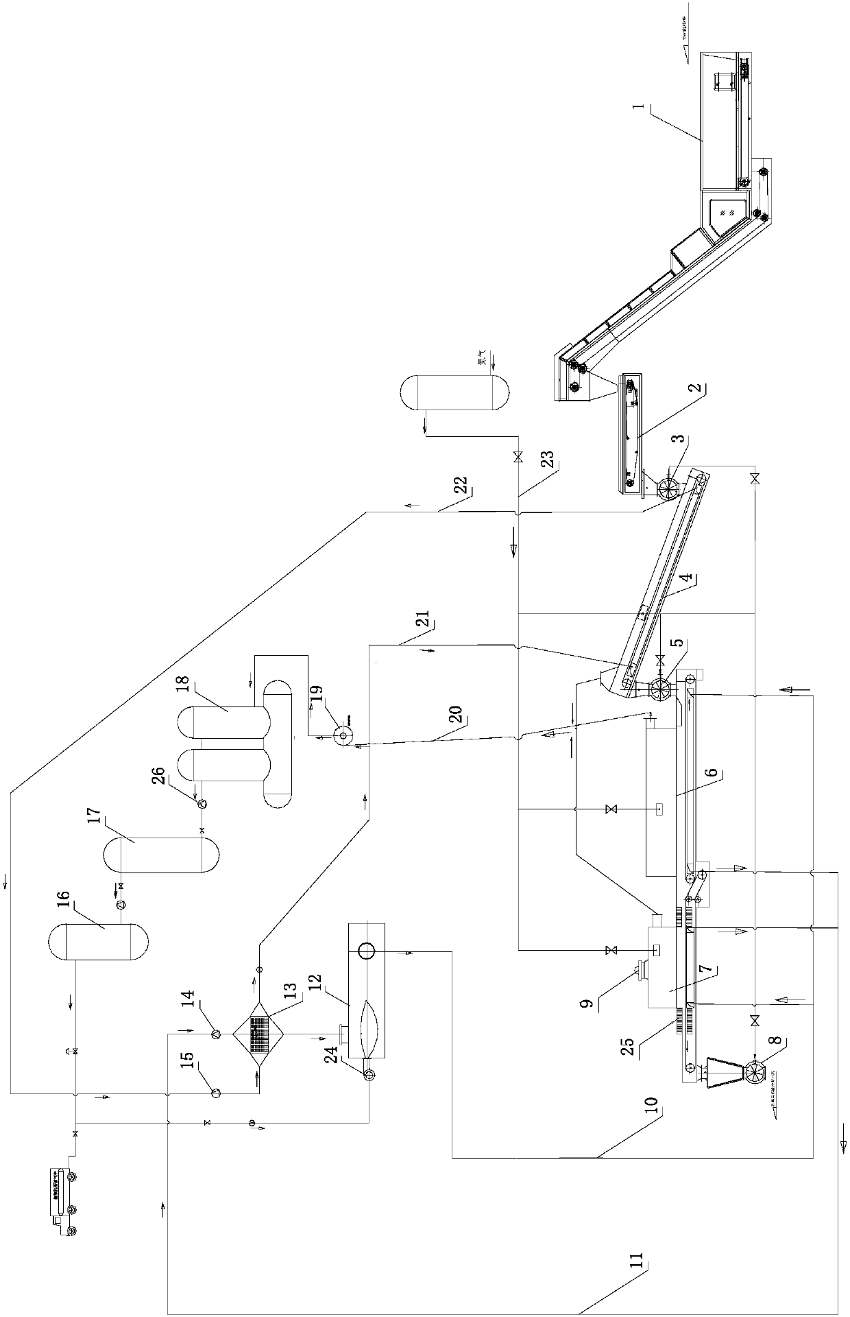
[0049] Such as figure 1 As shown, the cracking system of the present invention includes a feeding device, an oil and gas collection device, an oxygen removal device, a heating device, and a low-temperature thermal cracking chamber 4, a high-temperature thermal cracking chamber 6, a microwave cracking chamber 7, and a microwave cracking chamber that are sequentially sealed and connected. 7 is provided with a microwave source 9, and the inlet and outlet ends of the microwave cracking chamber 7 are also provided with a suppressor 25 to prevent microwave leakage; the low-temperature thermal cracking chamber 4, the high-temperature thermal cracking chamber 6, and the microwave cracking chamber 7 are all provided with stainless steel mesh belt conveyor. The discharge end of the low-temperature thermal cracking chamber 4 is higher than the feed end of the high-temperature thermal cracking chamber 6, and is connected through a nitrogen-sealed rotary valve B5. The high-temperature the...

Embodiment 2

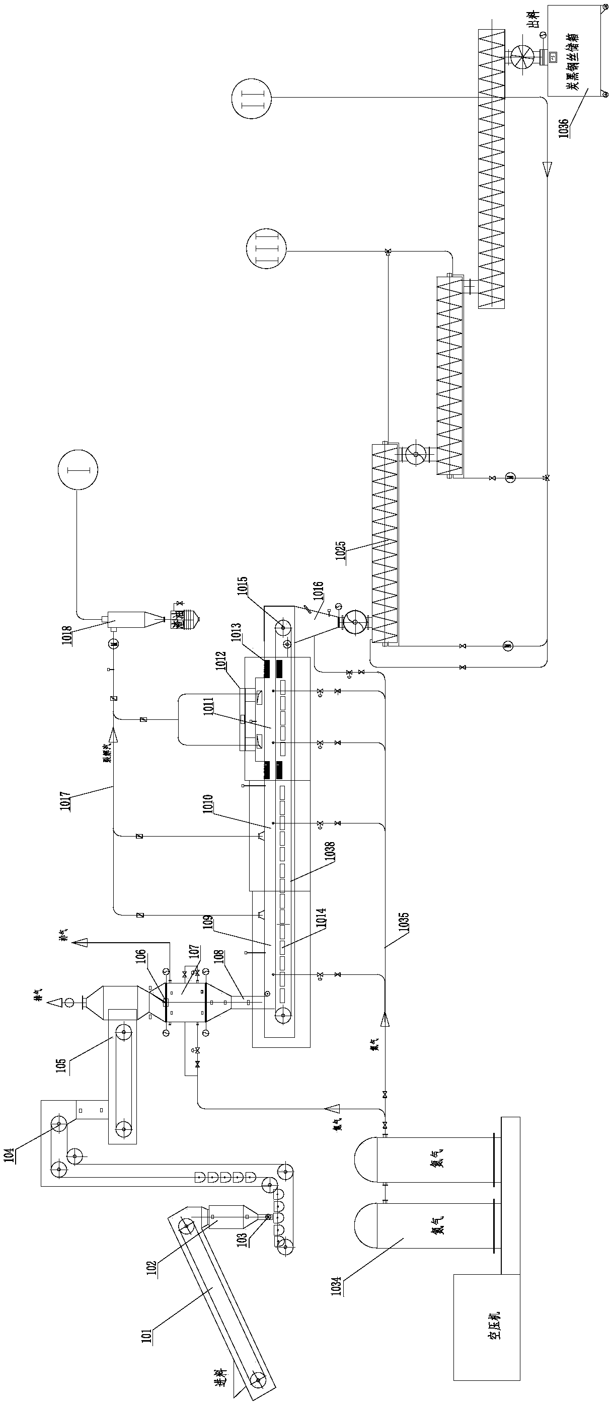
[0061] Such as image 3 , 4 As shown, the cracking system of the present invention includes a feeding device, an oil and gas collecting device, an oxygen removal device, a heating device, and a low-temperature thermal cracking chamber 109 connected in series, a high-temperature thermal cracking chamber 1010, a microwave cracking chamber 1011, and a microwave cracking chamber 1011 is provided with a microwave source 1012, and the inlet and outlet ends of the microwave cracking chamber 1011 are also provided with a suppressor 1013 to prevent microwave leakage; the low-temperature thermal cracking chamber 109, the high-temperature thermal cracking chamber 1010, and the microwave cracking chamber 1011 share a stainless steel mesh belt for conveying Machine 1038.

[0062] The feeding device includes a belt conveyor 101, a storage bin 102, a feeding roller 103, a hoist 104, a belt scale 105, a material guide plate 106, an alternate deoxygenation bin 107, and a feeding pipe 108. Th...


PUM


Abstract

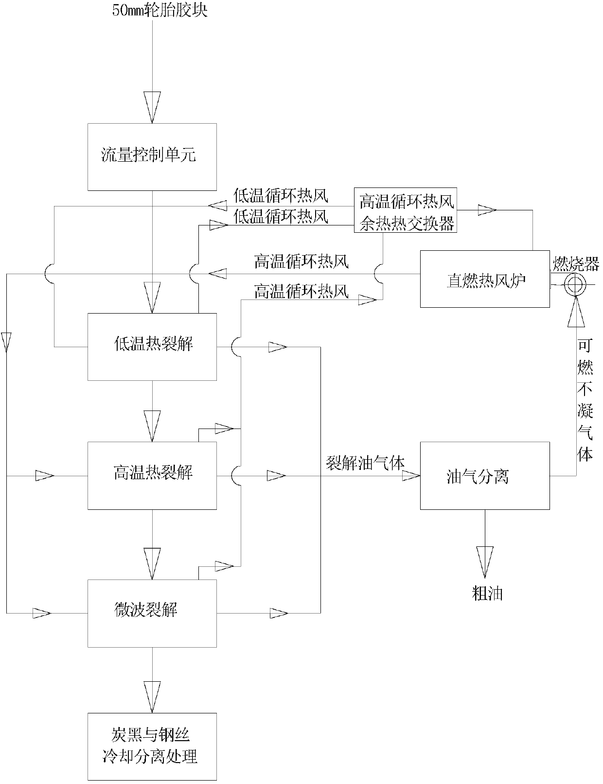
The invention provides a method and a system for cracking waste rubber. The waste rubber is sequentially sent to a low-temperature thermal cracking chamber, a high-temperature thermal cracking chamberand a microwave cracking chamber which respectively have an oxygen-free or oxygen-deficient environment, wherein thermal cracking of the waste rubber in the low-temperature thermal cracking chamber is carried out in a 200-400 DEG C environment, thermal cracking in the high-temperature thermal cracking chamber is carried out in a 500-800 DEG C environment, and microwave cracking in the microwave cracking chamber is carried out in a 500-800 DEG C environment; a cracking oil gas generated in the cracking process is continuously discharged from the low-temperature thermal cracking chamber, the high-temperature thermal cracking chamber and the microwave cracking chamber; and solids generated in the cracking process are recovered. The method and the system can effectively reduce the energy consumption in the cracking process and improve the cracking efficiency of the waste tire and the quality of cracked carbon black.

Description

technical field [0001] The invention relates to a waste rubber cracking method and system, in particular to a composite cracking method combining heat transfer cracking and microwave cracking, which can be used for cracking waste tires and the like, and belongs to the technical field of circular economy and energy saving and emission reduction. Background technique [0002] With the mass production of waste tires, the recycling and processing industry of waste tires has made great progress. my country produces nearly 400 million waste tires every year, and it is necessary to vigorously develop the recycling and processing industry of waste tires. At present, my country's waste tires are mainly used to produce reclaimed rubber and rubber powder. Reclaimed rubber production consumes a lot of energy and causes heavy pollution, and is gradually being eliminated worldwide. Rubber powder products have not yet been widely used in my country's market, and production capacity is limit...

Claims


Application Information

Patent Timeline
Patent Type & Authority Applications(China)
IPC IPC(8): C10G1/10C08J11/12B09B3/00C09C1/48
CPCC10G1/10C08J11/12C09C1/482B09B3/00C10G2300/1003B09B3/40Y02W30/62
Inventor 马铁兵杜国栋曾葆青黎晓云高永娣吴伏立王永金胡广伟董伟
Owner 江苏林达智思环保科技有限公司
Learn More