A kind of silicon rod cutting method

A cutting method and a technology of silicon rods, which are applied in the field of solar cells, can solve problems such as chipping, process loss, and the production cost of cells that affect the yield of silicon wafers, so as to improve the yield rate, increase the fracture resistance, reduce the generation and extended effect

Inactive Publication Date: 2020-07-10
CSI CELLS CO LTD +2
View PDF8 Cites 0 Cited by
  • Summary
  • Abstract
  • Description
  • Claims
  • Application Information

AI Technical Summary

Problems solved by technology

However, silicon crystal is a material with high hardness and high brittleness. During the diamond wire cutting process, defects such as edge chipping, silicon falling and process loss are prone to occur, accounting for 3%-4% of the total loss of silicon wafers, seriously affecting silicon wafers. The yield rate and the production cost of the cell
The main reason for the above-mentioned defects in silicon wafers is that the surface of silicon rods is prone to micro cracks or stress concentration to cause silicon wafer gaps, which induce edge chipping, silicon falling and debris.

Method used


Image

  • A kind of silicon rod cutting method
  • A kind of silicon rod cutting method
  • A kind of silicon rod cutting method

Examples


Embodiment 1

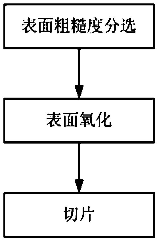
[0026] like figure 1 As shown, this embodiment provides a method for cutting a silicon rod. The silicon rod is sliced ​​after surface oxidation treatment. The surface of the silicon rod is oxidized before slicing, so that a dense oxide film is formed on the surface of the silicon rod. The oxide film can repair the defects on the surface of the silicon rod, and the hardness of the oxide film is low, which can protect and buffer the silicon rod. It plays the role of passivation, thereby reducing the generation and expansion of surface cracks, and improving the fracture resistance of silicon rods. During the slicing process, the force of diamond wire cutting is not enough to cause chipping and silicon drop And other defects, reduce process loss, reduce the proportion of silicon wafer chipping, and improve the yield of processed silicon wafers.

[0027] The surface oxidation of silicon rods can be oxidation of silicon rods in strong oxidizing solution or gas, or high temperature ...

Embodiment 2

[0043] This embodiment provides a method for cutting silicon rods, which is substantially the same as the method for cutting silicon rods in Embodiment 1. The difference from Embodiment 1 is that in this embodiment, the silicon rods are oxidized in a strong oxidizing gas.

[0044] Specifically, the silicon rod 5 can also be oxidized in a strong oxidizing gas such as ozone. When silicon rod 5 is oxidized in ozone, the concentration of ozone can be 1.2-1.5mg / L, for example can be 1.2mg / L, 1.3mg / L, 1.4mg / L, 1.5mg / L, wherein, the present embodiment The concentration of ozone in the medium is preferably 1.5mg / L. The oxidation time of the silicon rod 5 is 10min-60min, and the oxidation temperature is 10°C-200°C. Specifically, the oxidation time of silicon rod 5 can be 10min, 15min, 20min, 30min, 40min, 50min, 60min, and the oxidation time is preferably 15min; the oxidation temperature can be 10°C, 30°C, 50°C, 70°C, 90°C, 110°C, 130°C, 150°C, 170°C, 190°C, 200°C, the oxidation temp...

Embodiment 3

[0047] This embodiment provides a silicon rod cutting method, which is roughly the same as the silicon rod cutting method in Embodiment 1. The difference from Embodiment 1 and Embodiment 2 is that in this embodiment, the silicon rod is in air or oxygen. high temperature oxidation.

[0048] Silicon rod 5 can be placed in air or oxygen for high-temperature oxidation. The higher reaction temperature can compensate for the oxidation of air or oxygen. When silicon rod 5 is oxidized at high temperature in air or oxygen, the oxidation time of silicon rod 5 is 0.01min -60min, the oxidation temperature is 600°C-1400°C. Specifically, the oxidation time of silicon rod 5 can be 0.01min, 10min, 20min, 30min, 40min, 50min, 60min, and the oxidation time is preferably 30min; the oxidation temperature can be 600°C, 680°C, 760°C, 840°C, 920°C , 1000°C, 1080°C, 1160°C, 1240°C, 1320°C, 1400°C, the oxidation temperature is preferably 840°C.

[0049] Silicon rods are subjected to high-temperature...


PUM

PropertyMeasurementUnit
surface roughnessaaaaaaaaaa
tensionaaaaaaaaaa

Abstract

The invention discloses a silicon rod cutting method. A silicon rod is sliced after being subjected to surface oxidization treatment. In the silicon rod cutting method, the silicon rod is subjected tosurface oxidization treatment before being sliced, a layer of compact oxidation film is formed on the surface of the silicon rod, and the oxidation film can repair the defects on the surface of the silicon rod. The hardness of the oxidation film is low, the functions of protection and buffer can be achieved on the silicon rod, a passivation effect can be achieved, and therefore generation and expansion of surface cracks are reduced, and the breaking resisting strength of the silicon rod is improved. In the slicing process, the acting force of diamond wire cutting is not enough for generatingthe defects such as collapsing and silicon falling to the edges of silicon slices, the manufacturing loss is reduced, the proportion of silicon slice collapsing is reduced, and the yield of the processed silicon slices is improved.

Description

technical field [0001] The invention relates to the technical field of solar cells, in particular to a silicon rod cutting method. Background technique [0002] As the energy crisis and environmental problems such as smog and greenhouse effect become more and more serious, energy transformation is imminent. Due to the advantages of clean, pollution-free and large reserves of photovoltaic energy, the photovoltaic industry has received strong support from governments of various countries, has made great progress in technology, and has been more and more widely used. Solar energy has become one of the most promising new energy sources today. . [0003] In the past ten years, with the escalation of photovoltaic trade disputes and market fluctuations, the photovoltaic industry has experienced overcapacity, but the market demand for photovoltaic clean energy will continue to increase steadily, and photovoltaic power generation has entered the era of large-scale promotion and appl...

Claims


Application Information

Patent Timeline
Patent Type & Authority Patents(China)
IPC IPC(8): B28D5/00B28D5/04
CPCB28D5/0058B28D5/045
Inventor 熊震王君林李飞龙朱军邢国强
Owner CSI CELLS CO LTD
Why Eureka
Try Eureka