Low-carbon alkane chemical chain oxydehydrogenation to olefin technology

A carbon alkane chemical and oxidative dehydrogenation technology, applied in the direction of physical/chemical process catalysts, organic chemistry, chemical recovery, etc., can solve the problems of product cooling, high separation cost, decreased olefin selectivity, and difficult separation of by-products, etc., to achieve The effect of reducing catalyst carbon deposition, eliminating potential safety hazards, and reducing reaction energy consumption

Inactive Publication Date: 2018-05-18
CHINA UNIV OF PETROLEUM (EAST CHINA)
View PDF11 Cites 12 Cited by
  • Summary
  • Abstract
  • Description
  • Claims
  • Application Information

AI Technical Summary

Problems solved by technology

[0003] Patents CN 107428636 A, JP 2010-90083 A describe a method for producing butadiene by oxidative dehydrogenation of n-butene. Both methods use a mixed feed of n-butene and oxygen, and simultaneously feed a large amount of inert gas such as nitrogen to avoid explosion hazards , this feeding method requires a large amount of high-cost concentrated nitrogen as a protective gas
At the same time, in an oxygen atmosphere, hydrocarbons are prone to various side reactions at high temperatures, such as deep oxidation reactions or the formation of various high-boiling sediment components, which not only leads to a significant drop in olefin selectivity, but also cools and sepa

Method used


Image

  • Low-carbon alkane chemical chain oxydehydrogenation to olefin technology
  • Low-carbon alkane chemical chain oxydehydrogenation to olefin technology
  • Low-carbon alkane chemical chain oxydehydrogenation to olefin technology

Examples


example 1

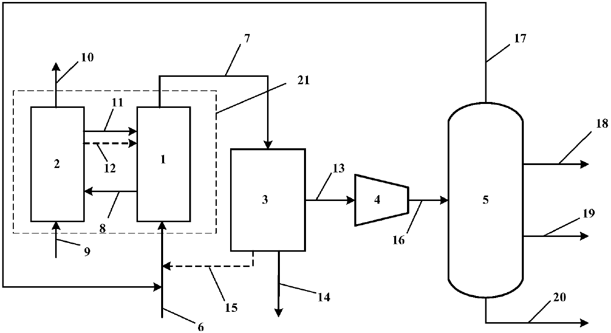
[0027] Such as figure 2 Shown are two side-by-side fixed bed propane chemical looping oxidative dehydrogenation to propylene systems. Compared with the reactor in which the catalyst particles are in a flowing state, the catalyst in the fixed bed reactor is not easy to lose, the gas flow is similar to plug flow, and the residence time of the reactants can be strictly controlled, and it is easy to obtain high conversion and selectivity. The reaction system includes:

[0028] Chemical chain oxidation dehydrogenation reactor 1: it has a propane raw material gas inlet, a reaction product outlet and a catalyst inlet. The propane raw material gas 6 is a mixture of 25% propane and 75% nitrogen, all of which are volume fractions, and is passed through the raw material gas inlet. Dehydrogenation reactor 1, the catalyst is loaded into the bed of reactor 1, the temperature of reactor 1 is 550°C, the pressure is normal pressure, the reaction product 7 is obtained after the oxidative dehy...

example 2

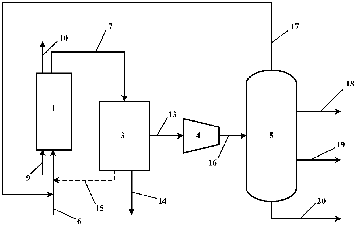
[0036] The process can also use a single fixed-bed reactor. in such as image 3 The shown single fixed-bed reactor unit carries out the propane chemical looping oxidative dehydrogenation to propylene process. This process is a batch operation process. The catalyst is loaded into the bed of the reactor 1, and the reaction raw material gas 6 is fed in, which is a mixed gas of 25% propane and 75% nitrogen, both in volume fraction. Reactor 1 temperature is 550 ℃, and pressure is normal pressure, and after reaction carries out 4h, catalyst loses activity, close propane inlet valve at this moment, feed a small amount of nitrogen to purge reaction gas in the device, close nitrogen inlet valve, Air 9 is introduced, and the catalyst is oxidized and regenerated at 550°C and atmospheric pressure. After regeneration, the oxygen-poor air 10 is discharged through the air outlet on the top of the reactor. The reaction time of oxidative regeneration is 1h. After the oxidation and regenerati...

example 3

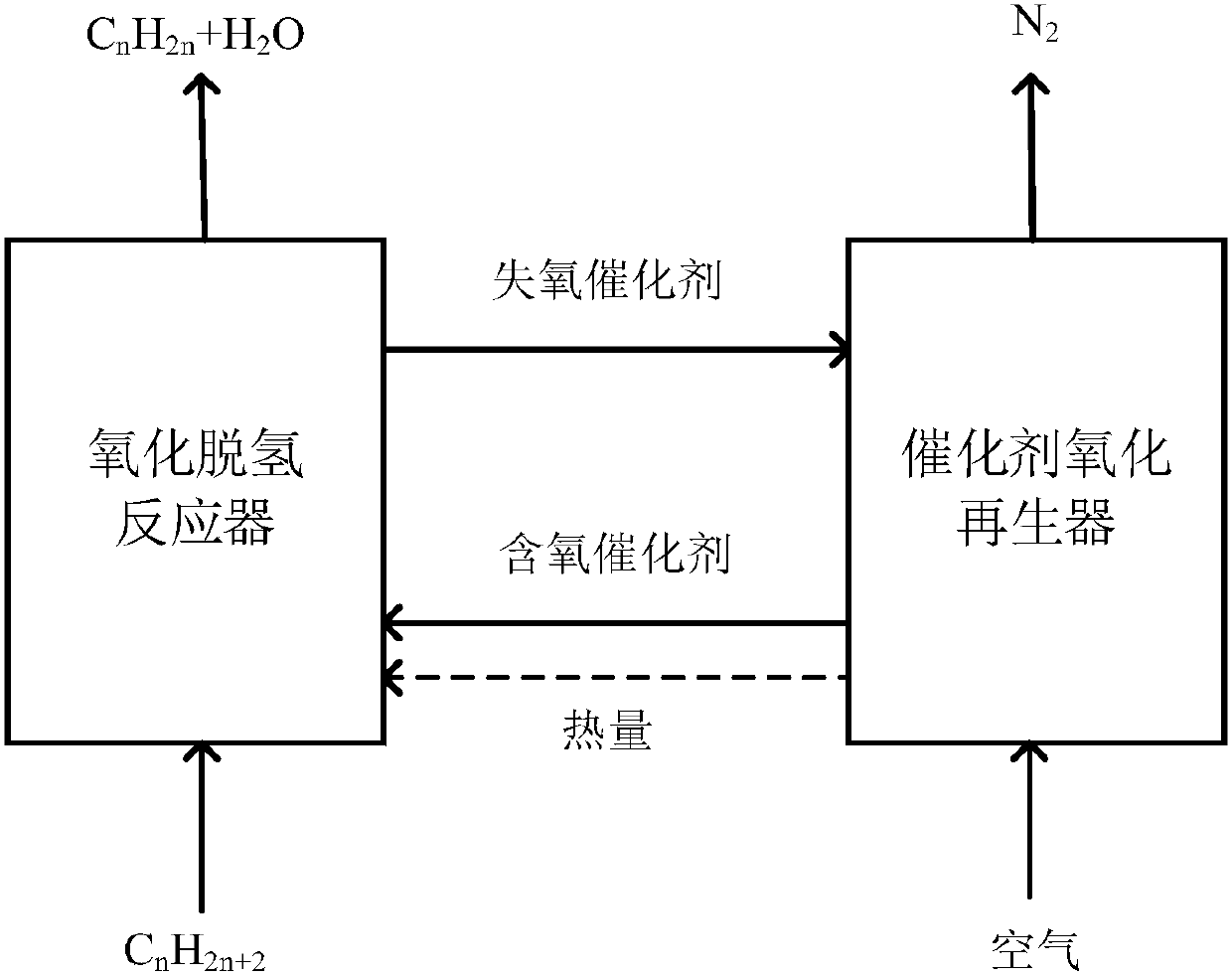
[0038] Figure 4 Shown is the process flow of chemical looping oxidative dehydrogenation of propane to propylene in a moving bed reactor device. The quenching unit 3, the compression unit 4, the separation unit 5 and the accompanying figure 2 Same process as shown, with Figure 4 will not be repeated. The reaction and regeneration process of the moving bed chemical chain oxidative dehydrogenation are carried out in the reactor and the regenerator respectively. The solid catalyst is continuously added from the top of the reactor, and as the reaction progresses, the solid catalyst gradually moves down by gravity, and finally is continuously discharged from the bottom. When a moving bed reactor is used, the solid-phase catalyst can move in the reactor and continuously enter and exit the reactor. The gas pressure drop is smaller than that of the fixed bed, and the back mixing is small. The solid residence time is between the fixed bed and the fluidized bed. and can vary over ...


PUM


Abstract

The invention relates to a design of low-carbon alkane (C2-C5) chemical chain oxydehydrogenation to olefin technology. A catalyst adopted by the technology is a novel bifunctional catalyst, a metallicoxide with an oxygen-carrying function is used as an oxygen carrier to provide lattice oxygen for oxidative dehydrogenation, and a metal active ingredient with a dehydrogenation function is loaded onthe metallic oxide. According to the technology, a fixed bed, a circulating fluidized bed or a moving bed can be taken as a reactor, in the oxidative dehydrogenation process, the metal active ingredient can be taken as a dehydrogenation active center, the reaction of dehydrogenation of alkane to olefin is taken place in the reactor, the lattice oxygen carried by the oxygen carrier can be selectively reacted with H2 generated in the dehydrogenation to oxidize the H2 to steam, when the reaction is completed, the catalyst losing the lattice oxygen is oxidized and regenerated in the air to supplement the lattice oxygen while carbon deposit is removed, and the reactivity of the catalyst is recovered. Compared with a traditional technology, in situ oxidation is conducted on the H2 generated inthe dehydrogenation to greatly improve percent conversion of the alkane and olefin yield, demands of catalytic reaction and catalyst regeneration can be met simultaneously, the dehydrogenation can beconducted at a lower temperature, the oxidized and regenerated catalyst carries a large amount of heat which can be provided for the dehydrogenation to achieve an operation of self-heating in the dehydrogenation process, and energy consumption can be greatly reduced by means of the designs.

Description

technical field [0001] The invention relates to the technical field of catalytic dehydrogenation, in particular to a process for producing olefins by chemical chain oxidative dehydrogenation of low-carbon alkanes. Background technique [0002] In recent years, the demand for low-carbon olefins in the petrochemical industry has been increasing, and the traditional naphtha cracking and catalytic cracking processes to obtain low-carbon olefins can no longer meet market demand. Therefore, seeking reasonable and efficient olefin production methods has become a national and global The urgent need of petrochemical enterprises. The technology of catalytic dehydrogenation of low-carbon alkanes to olefins has attracted much attention. The successful development of low-carbon alkane dehydrogenation to olefins technology can not only improve the utilization rate of oil and gas resources, but also produce high value-added low-carbon olefin products. The development of this technology An...

Claims


Application Information

Patent Timeline
IPC IPC(8): C07C11/06C07C5/333B01J38/10B01J38/12B01J38/02
CPCB01J38/02B01J38/10B01J38/12C07C5/3332C07C11/06Y02P20/52Y02P20/584
Inventor 白鹏杨苗苗吴萍萍阎子峰
Owner CHINA UNIV OF PETROLEUM (EAST CHINA)
Why Eureka
Try Eureka