Pollutant removal structure and combustion device suitable for domestic waste pyrolysis gasification gas

A technology of pyrolysis gasification and domestic waste, applied in the direction of combustion type, combustion method, incinerator, etc., can solve the problems of bed compaction, superheater contamination, affecting heat transfer efficiency, etc., and achieves ease of use, high flexibility, The effect of control system simplification

Active Publication Date: 2019-08-13
HUAZHONG UNIV OF SCI & TECH
View PDF5 Cites 0 Cited by
  • Summary
  • Abstract
  • Description
  • Claims
  • Application Information

AI Technical Summary

Problems solved by technology

The use of calcium spraying in the furnace to remove sulfur oxides in the combustion process is widely used in fluidized bed incineration systems. Calcium-based substances also have a certain dechlorination ability at temperatures above 850 ° C, but the injected calcium-based substances are likely to cause bed formation. Compaction, the by-product alkali metal calcium salt is easy to contaminate the heating surface of the superheater, affecting the efficiency of convective heat transfer

Method used


Image

  • Pollutant removal structure and combustion device suitable for domestic waste pyrolysis gasification gas

Examples


Embodiment Construction

[0024] In order to make the object, technical solution and advantages of the present invention clearer, the present invention will be further described in detail below in conjunction with the accompanying drawings and embodiments. It should be understood that the specific embodiments described here are only used to explain the present invention, not to limit the present invention. In addition, the technical features involved in the various embodiments of the present invention described below can be combined with each other as long as they do not constitute a conflict with each other.

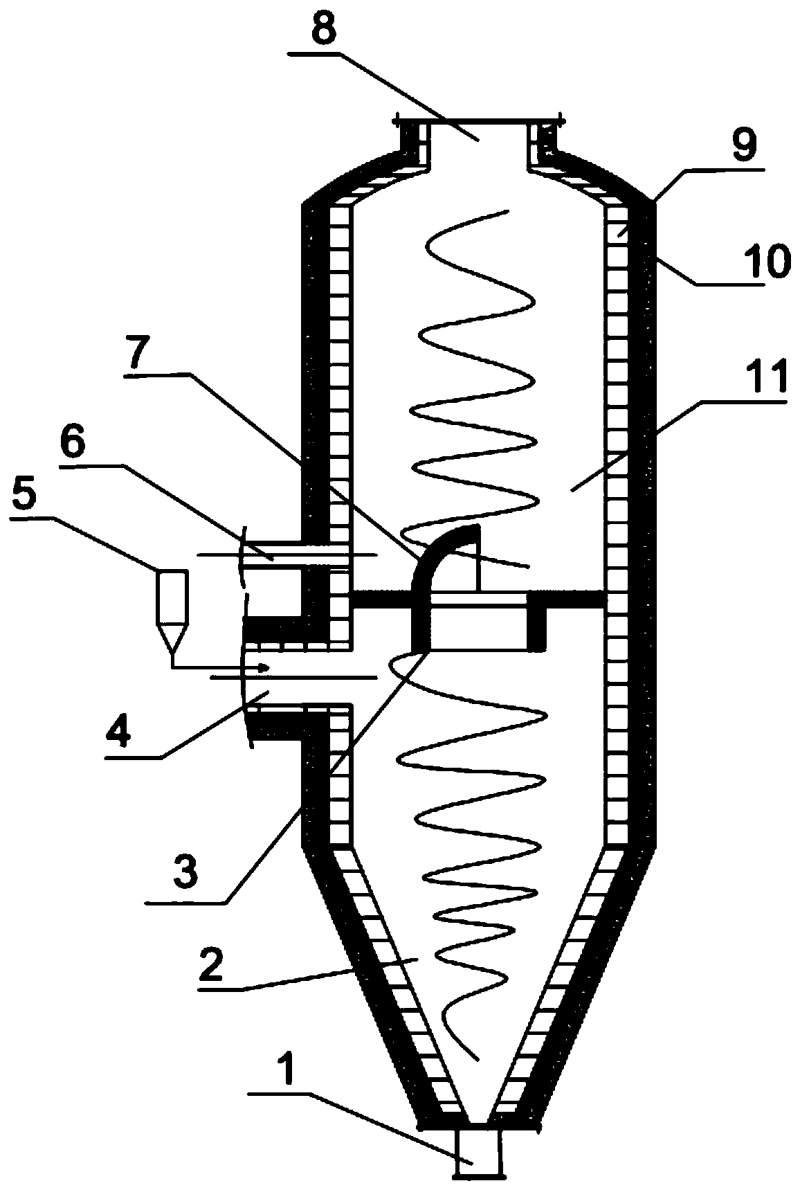
[0025] see figure 1 , the pollutant removal structure suitable for domestic waste pyrolysis gasification provided by the preferred embodiment of the present invention, the pollutant removal structure includes a furnace body 11, an insulation layer 10, a refractory brick layer 9, and a primary air duct 4 , secondary air duct 6, primary cyclone 3, secondary cyclone 7 and calcium-based injector 5....


PUM


Abstract

The invention belongs to the relative technical field of domestic waste incineration and pollutant control, and discloses a pollutant removal structure suitable for domestic-waste-pyrolyzed gasification gas and a combustion device. The pollutant removal structure comprises a furnace body, and a chamber is formed in the furnace body. A support plate is arranged in the chamber, the chamber is divided into an upper chamber and a lower chamber by the support plate, and the upper chamber communicates with the lower chamber. The pollutant removal structure further comprises a calcium-based ejector and a primary air pipe, wherein the primary air pipe is arranged on the furnace body and communicates with the lower chamber; the calcium-based ejector is adjacent to the primary air pipe and is used for ejecting calcium-based materials into the primary air pipe; and the primary air pipe is used for enabling the domestic-waste-pyrolyzed gasification gas and primary air to enter the lower chamber and to be desulfurized and dechlorinated at above 850 DEG C. The pollutant removal structure reduces dioxin emission, solves the problems of contamination and dust stratification, and has the advantagesof simple structure and high flexibility.

Description

technical field [0001] The invention belongs to the technical field related to pollutant control of domestic waste incineration treatment, and more specifically relates to a pollutant removal structure and a combustion device suitable for pyrolysis gasification of domestic waste. Background technique [0002] Incineration, as an effective means of reducing volume and volume of waste disposal, has been increasingly widely used. However, the waste incineration process will inevitably produce secondary pollution, including dioxins, hydrogen sulfide, hydrogen chloride, and fly ash, which are extremely harmful to the environment. These pollutants have a great impact on the environment and also cause harm to the human body. Therefore, solving the secondary pollutants produced in the waste incineration process is a major problem in waste disposal. [0003] Studies have shown that dioxins produced during waste incineration are closely related to transition metal chloride salts, HC...

Claims


Application Information

Patent Timeline
Patent Type & Authority Patents(China)
IPC IPC(8): F23G5/027F23G5/50F23J15/00F23J15/02
CPCF23G5/027F23G5/50F23J15/003F23J15/027
Inventor 陈汉平罗博刘英鹏张雄邵敬爱王贤华杨海平陈应泉张世红
Owner HUAZHONG UNIV OF SCI & TECH
Why Eureka
Try Eureka