
Preparation method of porous nano-optical fiber heterostructure photocatalysis filter net

A heterostructure, nano-fiber technology, applied in the field of nanomaterials, can solve the problems of low ability of filter screen to adsorb organic pollutants, low catalytic efficiency of photocatalytic materials, inability to make full use of sunlight, etc., so as to increase the specific surface area of ​​photocatalysis, Small size, the effect of increasing size and cost

Active Publication Date: 2018-06-05
SOUTHEAST UNIV
View PDF6 Cites 12 Cited by
  • Summary
  • Abstract
  • Description
  • Claims
  • Application Information

AI Technical Summary

Problems solved by technology

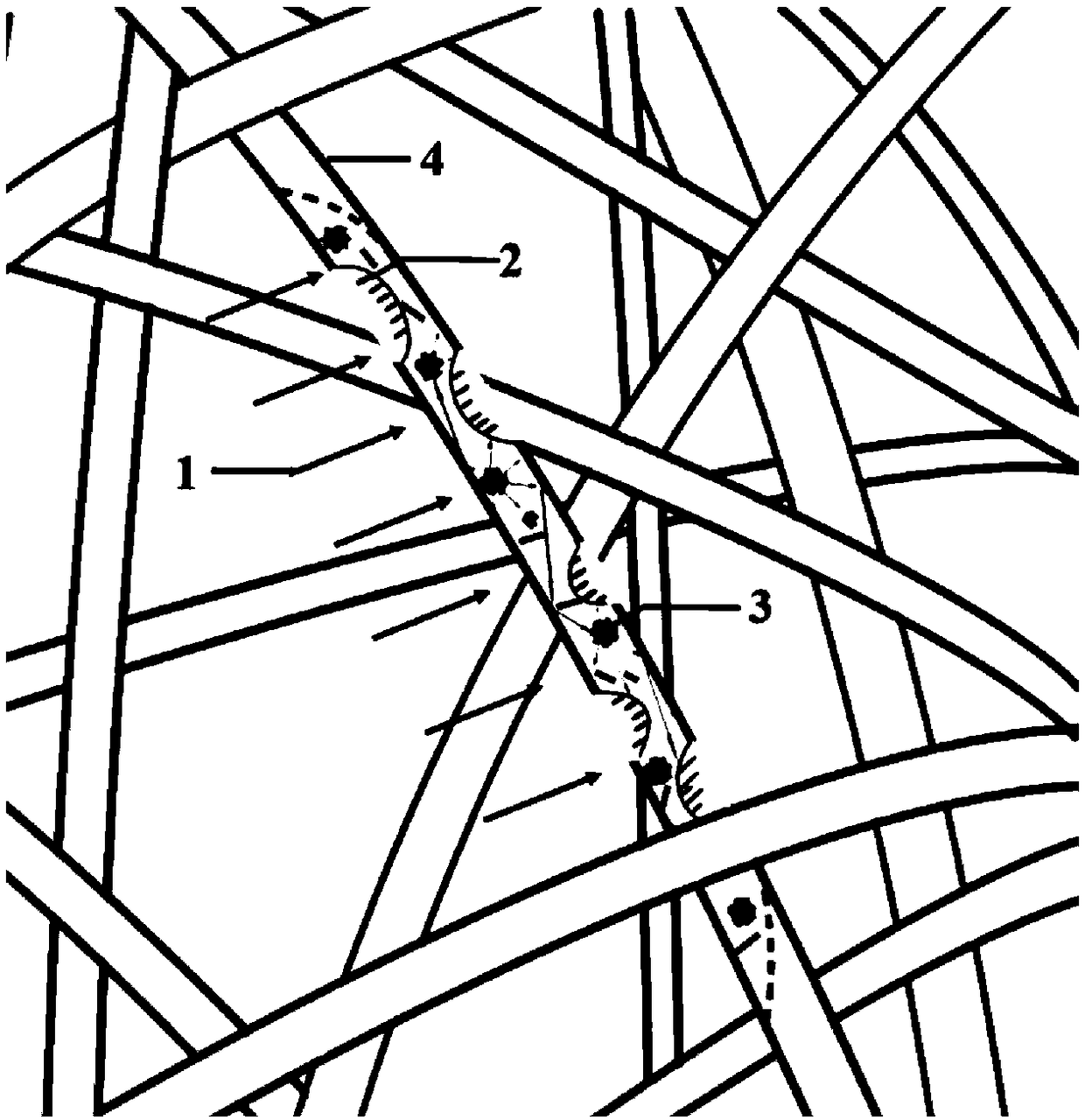
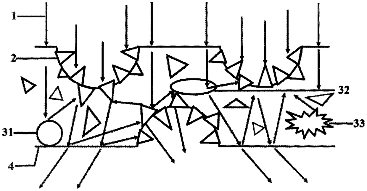
[0006] Technical problem: The purpose of this invention is to solve the problems of low catalytic efficiency of photocatalytic materials in traditional air purifiers, inability to make full use of sunlight, low ability of filter to absorb organic pollutants, short service life of purification system and high cost. A preparation method of a porous nano-fiber heterostructure photocatalytic filter based on an electronic mechanism. This filter structure can realize broad-spectrum line response in the sunlight band, high catalytic ability and multi-level full utilization of sunlight, and achieve broad-spectrum and high-efficiency. air purification

Method used


Image

  • Preparation method of porous nano-optical fiber heterostructure photocatalysis filter net
  • Preparation method of porous nano-optical fiber heterostructure photocatalysis filter net
  • Preparation method of porous nano-optical fiber heterostructure photocatalysis filter net

Examples


specific Embodiment 1

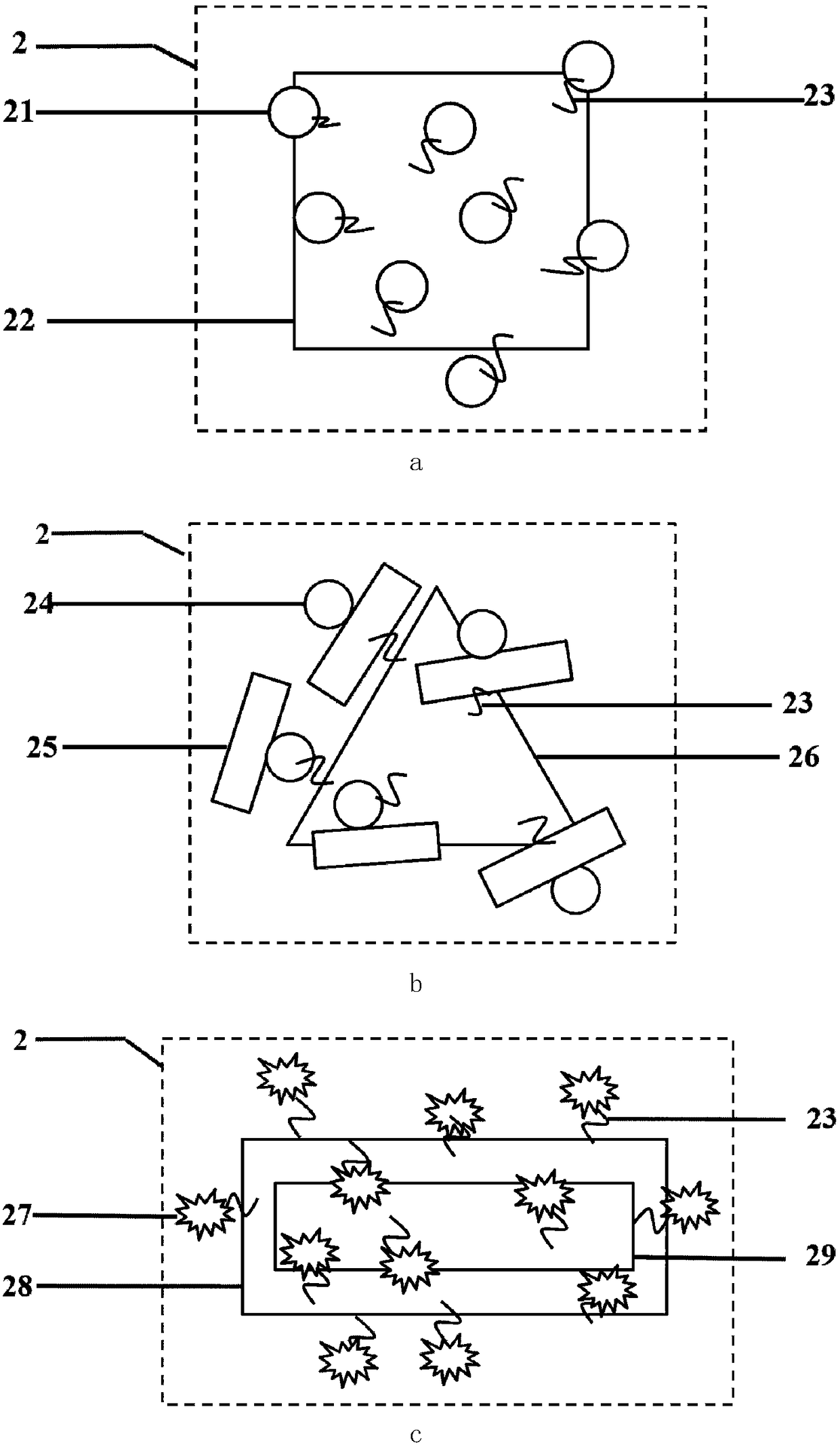
[0032] Step 1: Preparation of photocatalytic heterostructures composed of plasmonic metal nanostructures and semiconductor nanostructures with tunable spectra from visible to infrared bands

[0033] The gold nanocubes with tunable spectra in the visible to infrared bands were centrifuged three times at 4500 rpm for 15 min, the precipitate was dissolved in deionized water, and an initial solution a with a concentration of 0.1 mol / L was prepared. Centrifuge the cadmium sulfide nanosphere solution at 10,000rpm for 20min five times, dissolve the precipitate in deionized water, and configure it as an initial solution b with a concentration of 3mol / L; dissolve polyethylene glycol molecules in deionized water, and configure it with a concentration of 6mol / L initial solution c; take 20ml each of initial solution b and initial solution c, mix well, then centrifuge 3 times at 5000rpm for 15min, and dissolve the precipitate in deionized water to obtain a mixed solution d with a concentra...

specific Embodiment 2

[0039] Step 1: Preparation of photocatalytic heterostructures composed of plasmonic metal nanostructures and semiconductor nanostructures with tunable spectra from visible to infrared bands

[0040] Centrifuge the silver triangle solution with adjustable spectrum from visible to infrared band at 6000rpm for 25min twice, dissolve the precipitate in deionized water, and prepare initial solution a with a concentration of 0.5mol / L. The heterostructure solution composed of titanium dioxide nanorods and silver nanospheres was centrifuged three times at 8000rpm for 10min, and the precipitate was dissolved in deionized water to form an initial solution b with a concentration of 1mol / L; dimercapto-polyethylene glycol molecules Dissolve in deionized water and configure initial solution c with a concentration of 1mol / L; mix 20ml of initial solution b and initial solution c, stir thoroughly, then centrifuge 3 times at 6000rpm for 15min, and dissolve the precipitate in deionized water to ob...

specific Embodiment 3

[0046] Step 1: Preparation of photocatalytic heterostructures composed of plasmonic metal nanostructures and semiconductor nanostructures with tunable spectra from visible to infrared bands

[0047] Centrifuge the gold-silver alloy nanorod solution with adjustable spectrum from visible to infrared bands at 8000rpm for 15min three times, dissolve the precipitate in deionized water, and prepare initial solution a with a concentration of 2mol / L. Centrifuge the zinc oxide nanostar solution twice at 10,000rpm for 5min, dissolve the precipitate in deionized water, and configure the initial solution b with a concentration of 5mol / L; dissolve 3-aminopropyl triethoxy silicon in deionized water, Prepare the initial solution c with a concentration of 8mol / L; take 20ml each of the initial solution b and the initial solution c, mix them thoroughly, then centrifuge 3 times at 3000rpm and 10min, and dissolve the precipitate in deionized water to obtain a concentration of 5mol / L. mixed soluti...


PUM

PropertyMeasurementUnit
Diameteraaaaaaaaaa
Lengthaaaaaaaaaa
Sizeaaaaaaaaaa

Abstract

The invention discloses a preparation method of a porous nano-optical fiber heterostructure photocatalysis filter net. The preparation method comprises the following steps: preparing a spectrum-adjustable noble metal nano-structure and photocatalysis material heterostructure composite photocatalyst; and preparing a large-area and multilayer nano-optical fiber filter net structure, realizing the repeated conduction of sunlight in porous optical fibers by virtue of a scattering enhancement effect of metal nanoparticles in the porous optical fibers so as to realize interaction with the compositephotocatalyst on the surface, so that the photocatalytic efficiency is increased. According to the preparation method, an adjustable heterostructure composite photocatalyst with wide spectral responsefrom a visible light waveband to an infrared waveband is prepared, and meanwhile, an air purification filter net with high sunlight utilization rate and efficient catalytic degradation capacity is creatively disclosed by combining with the high absorbability and light translucency of the nano-optical fibers and the specific optical properties of the metal nanoparticles, so that the problems thata traditional air purification filter net is low in photocatalytic efficiency, short in service life, high in cost and the like are solved.

Description

technical field [0001] The invention relates to the fields of nanomaterials, photocatalysis and thin film devices, in particular to a porous nanofiber heterogeneous structure photocatalysis filter based on a thermal electron mechanism and a preparation method. Background technique [0002] In today's increasingly serious air pollution, the use of photocatalytic properties of semiconducting metal oxides for air purification is generally considered to have great development prospects. Traditional photocatalytic materials, such as titanium dioxide and zinc oxide, have attracted widespread attention because of their high chemical stability, environmental friendliness, simple process and low cost. Quantum efficiency (usually about 1%), large band gap can only respond to ultraviolet light (only 4% of the solar spectrum), unable to use visible or even infrared sunlight, and poor compatibility with traditional filter structures, etc. Many defects limit the application scenarios of ...

Claims


Application Information

Patent Timeline
IPC IPC(8): B01D39/14B01D53/44B01D53/86B01D53/74B01J31/26B01J31/38
CPCB01D39/14B01D53/44B01D53/74B01D53/86B01J31/26B01J31/38B01D2255/20792B01D2255/104B01D2255/106B01D2255/802B01J35/39B01J27/04B01D39/1623B01D2239/0414B01D2239/025B01D2239/0631B01D2239/10B01J31/1616B01D2258/06B01D53/885B01D2255/1023B01D2255/20707B01D2255/20738B01D2255/9202B01D2259/802B01D2259/80B01D53/8687B01J35/23B01J35/33B01J35/58B01D2255/1021B01D2255/9155B01J21/063B01J23/06B01J31/1608B01J31/1683B01J37/04B01J37/06B01J37/342B01J2231/005B01J2531/004B01J2531/17B01J2531/18B01J23/50B01J23/66B01J37/009B01J35/50B01J35/59
Inventor 张晓阳张彤王善江纪愚赵明虎赵临风
Owner SOUTHEAST UNIV
Learn More