Micro-fluidic chip based on fluorescence immunoassay joint detection as well as preparation method and application of micro-fluidic chip

A microfluidic chip and combined detection technology, which is applied in the direction of measuring devices, instruments, scientific instruments, etc., can solve the problems of cumbersome microfluidic preparation process, fluorescence signal acquisition interference, and affecting detection sensitivity, etc. Improvement of detection sensitivity, effect of increased sensitivity

Active Publication Date: 2018-06-19
BEIJING ELCOTEQ BIO TECH
View PDF9 Cites 14 Cited by
  • Summary
  • Abstract
  • Description
  • Claims
  • Application Information

AI Technical Summary

Problems solved by technology

[0003] In the past, the magnetic separation fluorescent microsphere technology used in immunochromatographic test strips or microfluidics, because a large number of fluorescent microspheres will be on the lower side of the magnetic microspheres during the immune reaction and rolling process, resulting in the blocking of the magnetic microspheres. Part of the fluorescent signal causes interference to the acquisition of the fluorescent signal, which greatly affects the detection sensitivity
[0004] In addition, the previous microfluidic chips used multiple microfluidic channels on a disk to achieve joint detection. The preparation process of this method is cumbersome and requires a large amount of samples for detection.

Method used


Image

  • Micro-fluidic chip based on fluorescence immunoassay joint detection as well as preparation method and application of micro-fluidic chip
  • Micro-fluidic chip based on fluorescence immunoassay joint detection as well as preparation method and application of micro-fluidic chip
  • Micro-fluidic chip based on fluorescence immunoassay joint detection as well as preparation method and application of micro-fluidic chip

Examples


Embodiment 1

[0084] Below, take the microfluidic chip for detecting serum amyloid A (SAA) and whole C-reactive protein (CRP) as an example, the present invention is described:

[0085] 1. Treatment of antibody-coated area

[0086] 1.1 Fluorescent microspheres label a mouse anti-human SAA monoclonal antibody

[0087] Take 5mL of 0.01g / mL latex fluorescent microspheres into a small centrifuge tube, centrifuge at 12000r / min for 20min, remove the supernatant, redissolve with 5mL of sodium carbonate buffer solution, and then add 5mg of carbon Diimine (EDC), 5 mg of N-hydroxysuccinimide (NHS) and 1 mL of a mouse anti-human SAA monoclonal antibody were stirred at 25 ° C for 6 h, and 2.5 mg of lysine was added and stirred at room temperature for 20 min , put the mixture into a dialysis bag and dialyze at 4°C for 12h; after the dialysis, centrifuge the mixed solution at 12000r / min for 10min, remove the supernatant, and finally reconstitute with 20mL of LM buffer solution for use.

[0088] 1.2 A m...


PUM

PropertyMeasurementUnit
particle diameteraaaaaaaaaa

Abstract

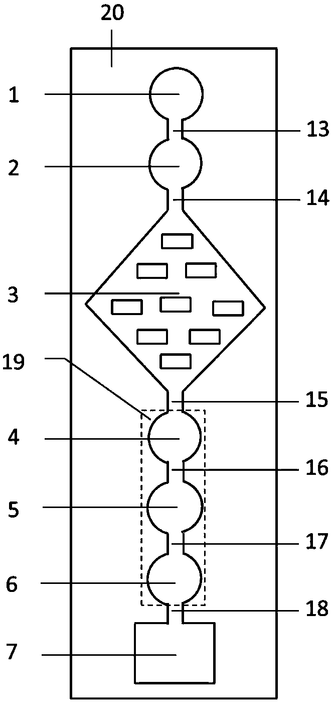
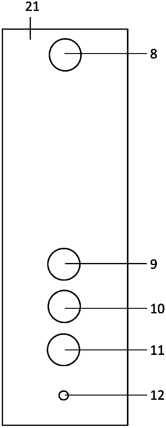
The invention relates to a micro-fluidic chip based on fluorescence immunoassay joint detection. The micro-fluidic chip comprises a chip substrate and an upper layer cover plate covering the upper part of the chip substrate; a sample adding zone, an antibody coating zone, a micro mixing zone, at least two detection zones, a quality control zone and a waste liquid collecting zone which are sequentially communicated by a capillary microchannel are arranged on the chip substrate; a sample adding hole, at least two detection windows, a quality control window and a ventilation hole are formed in the upper layer cover plate and sequentially correspond to the sample adding zone, the detection zones, the quality control zone and the waste liquid collecting zone. The invention also provides a preparation method and the application of the micro-fluidic chip. According to the micro-fluidic chip disclosed by the invention, immunomagnetic microspheres are arranged in the detection zone and the quality control zone, and to-be-detected substances are favorably fixed in the corresponding detection zones, so that the interference caused by non-specificity is reduced and the sensitivity is improved.

Description

technical field [0001] The invention belongs to the field of in vitro diagnosis, and in particular relates to a microfluidic chip based on fluorescence-immunity combined detection and its preparation method and application. Background technique [0002] In recent years, the field of bioanalysis technology has developed rapidly, and many important research directions have emerged. Microfluidic chip analysis technology is one of the most active ones, and has received extensive attention in both scientific research and application fields. As a new type of analysis and detection platform, microfluidic chips have the advantages of high throughput, integration, portability, easy operation, and low cost, and have been widely used in many fields. [0003] In the past, the magnetic separation fluorescent microsphere technology used in immunochromatographic test strips or microfluidics, because a large number of fluorescent microspheres will be on the lower side of the magnetic micro...

Claims


Application Information

Patent Timeline
Patent Type & Authority Applications(China)
IPC IPC(8): G01N33/533G01N33/543G01N33/558
CPCG01N33/533G01N33/54326G01N33/558
Inventor 林斯
Owner BEIJING ELCOTEQ BIO TECH
Why Eureka
Try Eureka