Lime kiln combined denitration system
A lime kiln and denitrification technology, which is applied in the field of lime kiln combined denitrification system and denitrification equipment, can solve the problems that cannot fully meet the quality requirements of lime kiln flue gas emission, achieve reduced atomization medium consumption, increased reaction time, and low ammonia water pressure Effect
- Summary
- Abstract
- Description
- Claims
- Application Information
AI Technical Summary
Problems solved by technology
Method used
Image

Examples
Embodiment 1
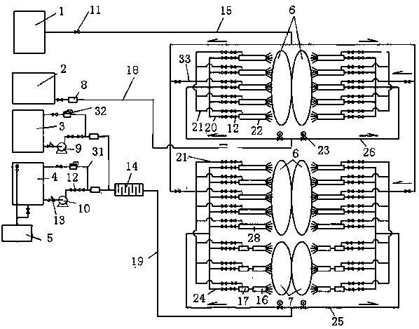
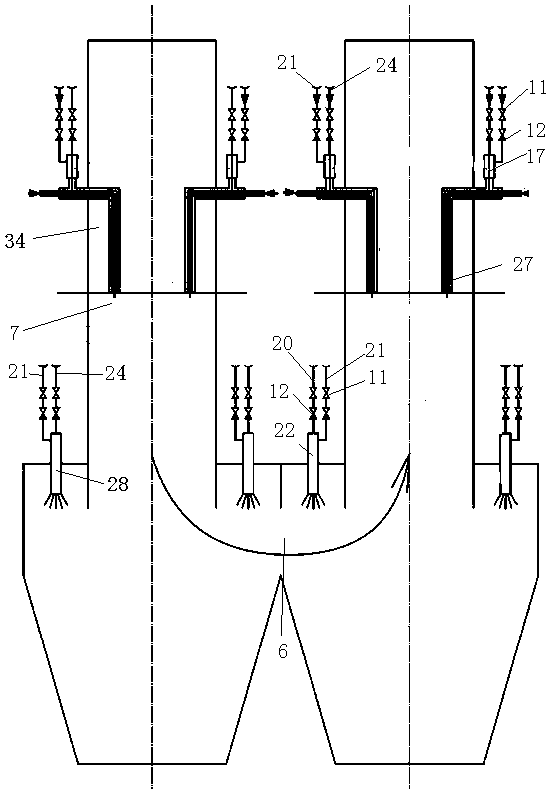
[0020] Lime kiln combined denitrification system of the present invention such as figure 1 As shown, it includes a compressed air storage tank 1, a reducing agent storage tank 2, a demineralized water storage tank 3, a denitration agent storage tank 4, a waste water treatment device 5, a static mixer 14 and a lime kiln. The reducing agent in the reducing agent storage tank 2 is hydrogen, and the denitrating agent in the denitrating agent tank is ammonia water. The denitration agent storage tank is equipped with an automatic overflow pipeline and a discharge pipeline, and is connected with the wastewater treatment device. The lime kiln is a double chamber kiln, such as figure 2As shown, the double-chamber kiln is provided with a channel 6 and a calcination zone 34, and the channel is provided with a reducing agent spray gun 22 and a denitrifying agent spray gun 28, and the reducing agent spray gun and the denitrating agent spray gun are arranged in the two kiln chambers of th...
Embodiment 2
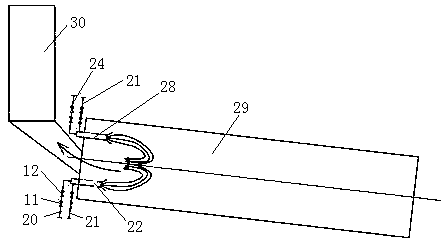
[0025] Another embodiment of the present invention is as image 3 As shown, the lime kiln is a rotary kiln 29, and the rotary kiln includes a kiln head, a kiln tail and a preheater 30, and the preheater is connected to the kiln tail. Reductant spray gun 22 and denitration agent spray gun 28 are arranged at the kiln tail. The reducing agent spray gun is provided with a reducing agent inlet and a compressed air inlet, and the denitration agent spray gun is provided with a denitrification agent inlet and a compressed air inlet. The compressed air storage tank is respectively connected to the compressed air inlet of the reducing agent spray gun and the denitration agent spray gun and the compressed air main pipe 15, the compressed air 33 branch pipe and the compressed air branch pipe 21. The reducing agent storage tank 2 is connected to the reducing agent inlet of each reducing agent spray gun through the reducing agent main pipe 18 , the reducing agent branch pipe 26 and the red...
Embodiment 3
[0027] Yet another embodiment of the present invention is as Figure 4 As shown, the lime kiln is a beam kiln 45, and the beam kiln includes a feed system 38, a kiln body and a discharge port 37. The kiln body is provided with a preheating zone 35 , a calcining zone 34 and a cooling zone 36 . The preheating zone is provided with an upper suction beam 39, the lower part of the upper suction beam is provided with a denitrification beam 41, the calcining zone is provided with a combustion beam 42, and the cooling zone is provided with a lower suction beam 43. The upper suction beam is provided with a denitration spray gun 40, the lower suction beam and the denitration beam are provided with a denitration channel 44, the denitration spray gun and the denitration channel are provided with a denitration agent atomizer, and the denitration agent atomizer is provided with a denitrification agent inlet and a compressed air inlet . The desalinated water storage tank is connected to th...
PUM
 Abstract
Description
Claims
Application Information
 - Generate Ideas
- Intellectual Property
- Life Sciences
- Materials
- Tech Scout
- Unparalleled Data Quality
- Higher Quality Content
- 60% Fewer Hallucinations
Browse by: Latest US Patents, China's latest patents, Technical Efficacy Thesaurus, Application Domain, Technology Topic, Popular Technical Reports.
© 2025 PatSnap. All rights reserved.Legal|Privacy policy|Modern Slavery Act Transparency Statement|Sitemap|About US| Contact US: help@patsnap.com