
High-temperature sewage waste heat recovery and high-efficiency reutilization process

A high-temperature sewage and waste heat technology, applied in degassed water/sewage treatment, water/sewage multi-stage treatment, water/sludge/sewage treatment, etc., can solve the problem of flue gas emission, large gas or fuel consumption, and discharge, etc. problems, to achieve the effect of reducing operating costs

Pending Publication Date: 2018-07-13
TIANJIN ZHENGFANG TECH DEV
View PDF0 Cites 2 Cited by
  • Summary
  • Abstract
  • Description
  • Claims
  • Application Information

AI Technical Summary

Problems solved by technology

[0003] The purpose of the present invention is to provide a method that uses the existing sewage waste heat resource of the combined station as a heat source, combined with a heat pump system, to raise the temperature of the incoming liquid crude oil of the combined station; uses the high-temperature sewage waste heat recovery technology to replace the gas heating furnace, and satisfies oil field production and life. Heat demand during activities, waste heat recovery and reuse system for waste water to solve environmental problems such as large gas or fuel consumption, carbon emissions and flue gas emissions

Method used


Image

  • High-temperature sewage waste heat recovery and high-efficiency reutilization process

Examples


Embodiment Construction

[0027] The specific embodiments of the present invention will be briefly described below in conjunction with the drawings.

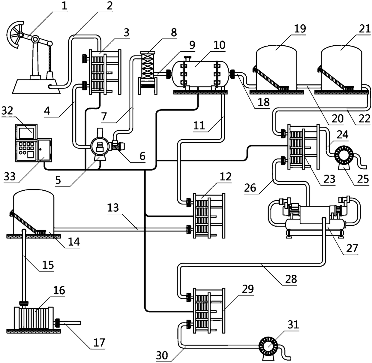
[0028] Such as figure 1 A process for recovering waste heat from high-temperature sewage and high-efficiency reuse is shown, which is characterized by: oil well 1, dehydration heat exchanger 3, heating furnace 5, filter 8, three-phase separator 10, and primary heat exchanger 12 , Buffer tank 14, water injection device 16, sedimentation tank 19, oil storage tank 21, secondary heat exchanger 23, ultra-high temperature heat pump 27, tertiary heat exchanger 29 and controller 32, the oil well 1 is also provided with The oil well inflow output pipe 2 is located on one side of the oil well 1, one end of the oil well inflow output pipe 2 is fixedly connected to the oil well 1, and the other end of the oil well inflow output pipe 2 It is fixedly connected to the dehydration heat exchanger 3, the dehydration heat exchanger 3 is located at one side of the oil well in...


PUM


Abstract

The invention aims at providing a high-temperature sewage waste heat recovery and high-efficiency reutilization process. According to the technical scheme of the process, an oil well, a dehydration heat exchanger, a heating furnace, a filter, a three-phase separator, a first-stage heat exchanger, a buffer tank, a water injection device, a settling tank, an oil storage tank, a second-stage heat exchanger, a superhigh-temperature heat pump, a three-stage heat exchanger and a controller are included. In the system, an existing sewage waste heat resource of a combination station is adopted as a heat source and is combined with a heat pump system to raise the temperature of coming crude oil of the combination station; the high-temperature sewage waste heat recovery technology is used for replacing a fuel gas heating furnace to meet the requirements for heat application during oil field production and life activities; through the sewage waste heat recovery and reutilization system, the environmental protection problems of the large fuel gas or fuel gas use amount, carbon emission and flue gas emission are solved. The whole system is clear in structure and can improve the utilization efficiency of the boiler through three stages of heat exchange. The operation cost is reduced. Emission of poisonous gas is reduced. The occupied area is reduced. The system is controlled full-automatically without a designate person on duty.

Description

Technical field [0001] The invention relates to the field of energy and environmental protection, in particular to a process for recovering waste heat of high-temperature sewage and high-efficiency reuse. Background technique [0002] On the one hand, a large amount of energy needs to be consumed in the production process of an oil field: First of all, the dehydration and export of crude oil need to be heated during the process from output to the output system of refined crude oil. It provides hot water to the wellhead and mixes oil and water. Three types of heat demand, such as liquid heating and finished crude oil heating, can be used for heating in dormitories, duty rooms, pump rooms, etc. of production plants and mines. At present, these heat needs are basically provided by water jacket heating furnaces fueled by natural gas and crude oil. The temperature range for heating crude oil is 40~70℃. This form of energy utilization actually uses burning high-grade energy to obtain l...

Claims


Application Information

Patent Timeline
Patent Type & Authority Applications(China)
IPC IPC(8): F25B30/06F28D21/00C02F9/02C02F103/10
CPCF25B30/06F28D21/00C02F9/00C02F1/40C02F1/001C02F1/20C02F2103/10C02F2001/007
Inventor 韩霞兰文沙金鑫孙文
Owner TIANJIN ZHENGFANG TECH DEV
Learn More