Rubber regenerative exhaust gas treatment device

A waste gas treatment device, rubber technology, applied in the direction of gas treatment, chemical/physical process, chemical/physical/physical chemical process, etc., can solve the problem of harmful tail gas pollution of the environment, achieve high combustion efficiency, exhaust gas incineration, and complete combustion Effect

Pending Publication Date: 2018-07-20
NANTONG HUILI RUBBER
View PDF1 Cites 1 Cited by
  • Summary
  • Abstract
  • Description
  • Claims
  • Application Information

AI Technical Summary

Problems solved by technology

[0005] In order to overcome the problem of environmental pollution caused by harmful tail gas produced by the regenerated rubber production process, the invention provides a rubber regenerated waste gas treatment device

Method used


Image

  • Rubber regenerative exhaust gas treatment device
  • Rubber regenerative exhaust gas treatment device
  • Rubber regenerative exhaust gas treatment device

Examples


Embodiment 1

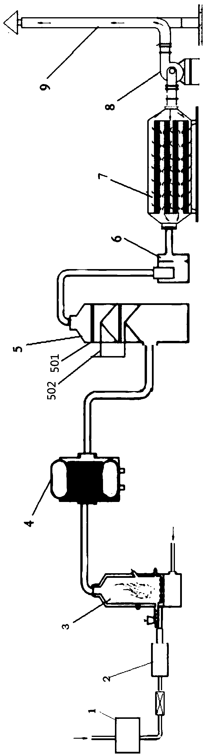
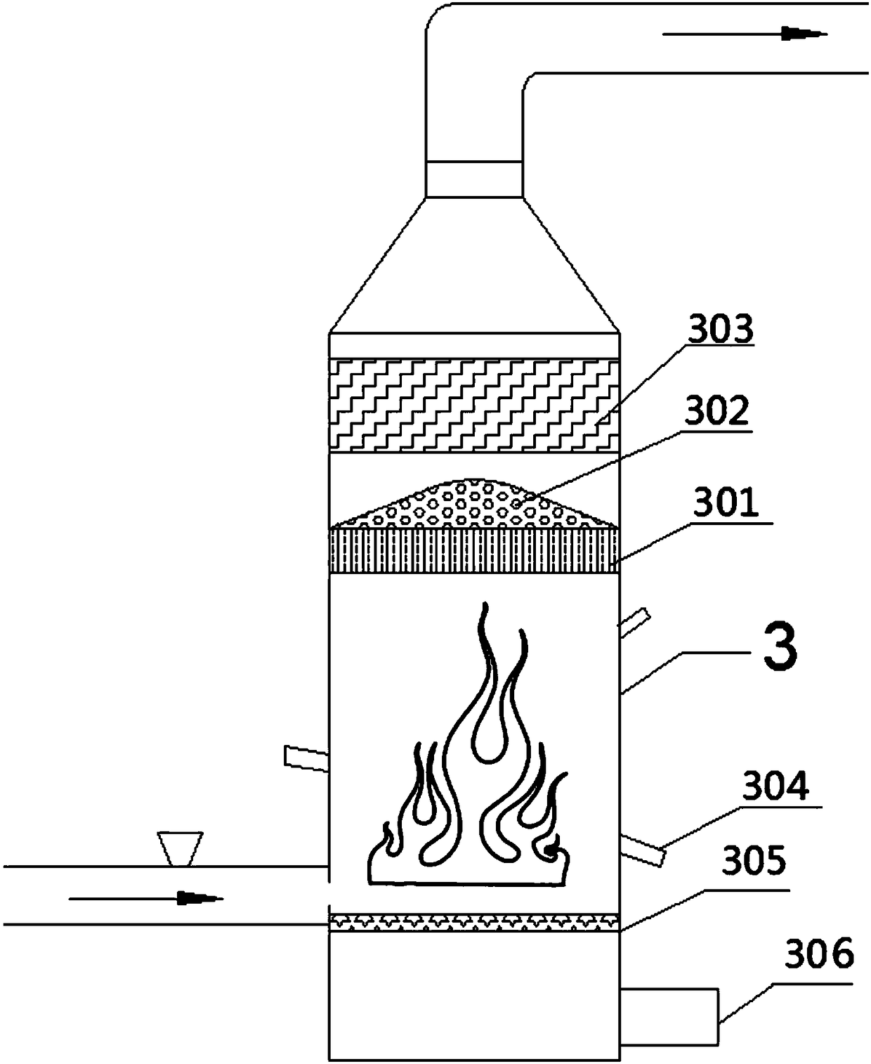
[0037] Such as figure 1 As shown, a rubber regeneration waste gas treatment device is characterized in that it includes an air supply system, an electric control system, and a waste gas filter device 1, a burner 2, an incinerator 3, and a flue gas heat-absorbing cooling tank connected in sequence through pipelines 4. Spray absorption tower 5, water and gas separator 6, dust removal filter device 7, chimney 9; exhaust gas passes through the exhaust gas filter device 1 and then enters the burner 1 through the pipeline, and enters the incinerator 3 for high-temperature incineration; the flue gas pipeline is in the flue gas The air heat absorption cooling tank 4 is curved and coiled inside, and the flue gas heat absorption cooling tank 4 is provided with a cold water inlet and a hot water outlet; the air supply system communicates with the incinerator 3 .

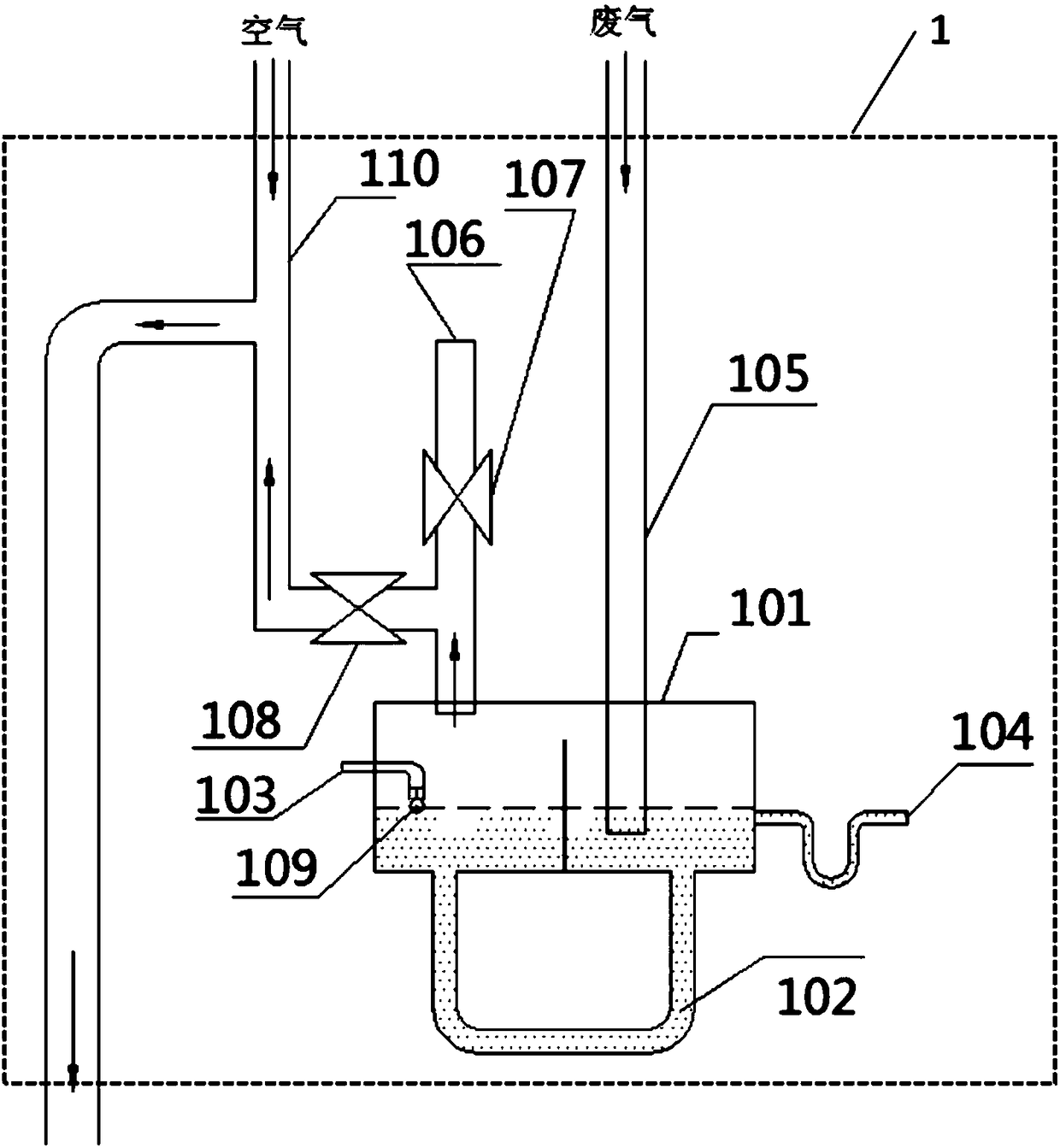
[0038] Such as figure 2 As shown, the waste gas filter device 1 includes a closed water storage tank 101, a U-shaped pipe 1...

Embodiment 2

[0046] Such as figure 1 As shown, a rubber regeneration waste gas treatment device is characterized in that it includes an air supply system, an electric control system, and a waste gas filter device 1, a burner 2, an incinerator 3, and a flue gas heat-absorbing cooling tank connected in sequence through pipelines 4. Spray absorption tower 5, water and gas separator 6, dust removal filter device 7, chimney 9; exhaust gas passes through the exhaust gas filter device 1 and then enters the burner 1 through the pipeline, and enters the incinerator 3 for high-temperature incineration; the flue gas pipeline is in the flue gas The air heat absorption cooling tank 4 is curved and coiled inside, and the flue gas heat absorption cooling tank 4 is provided with a cold water inlet and a hot water outlet; the air supply system communicates with the incinerator 3 .

[0047] In this embodiment, the structures and functions of the exhaust gas filter 1, the burner 2, the incinerator 3, the flu...


PUM

PropertyMeasurementUnit
Thicknessaaaaaaaaaa

Abstract

The invention provides a rubber regenerative exhaust gas treatment device which is characterized by comprising a supply air system, an electric control system, an exhaust gas filtering device, a combustion machine, an incinerator, a flue gas heat absorption cooling tank, a spray absorption tower, a water-gas separator, a dust-removing filter device and a chimney, wherein the exhaust gas filteringdevice, the combustion machine, the incinerator, the flue gas heat absorption cooling tank, the spray absorption tower, the water-gas separator, the dust-removing filter device and the chimney are sequentially connected through a pipe. Exhaust gas passes through the exhaust gas filtering device and then is led into the combustion machine through a pipe, and enters the incinerator for high-temperature incineration; a flue gas pipeline is bent and coiled in the flue gas heat absorption cooling tank, and the flue gas heat absorption cooling tank is provided with a cold water inlet and a hot wateroutlet; and the supply air system is communicated with the incinerator. The rubber regenerative exhaust gas treatment device is small in occupied area and high in combustion efficiency, waste heat energy can be recycled, and the effect of energy saving is achieved. The electric control system comprises a warning device, the warning device is connected with a photosensitive tube detection device in the combustion machine, and once flameout occurs or ignition fails, waste gas and an oil path are automatically cut off to prevent a safety accident.

Description

technical field [0001] The invention relates to the technical field of regenerated rubber, in particular to a rubber regenerated waste gas treatment device. Background technique [0002] Regenerated rubber is made of waste rubber as raw material by recycling technology. The regeneration process needs to go through a desulfurization process to change the plastic state of the waste rubber particle network structure and restore its soft rubber-like structure. Therefore, the exhaust gas discharged from the regeneration process contains H 2 S, benzene, toluene, xylene, non-methane total hydrocarbons and other volatile organic pollutants, as well as water vapor, a small amount of rubber powder particles, etc., the direct emission of exhaust gas will affect the surrounding environment and have a foul smell. [0003] The thermal combustion method has a high treatment efficiency and can treat high-concentration waste gas at one time. For example, Chinese patent CN206853436U disclose...

Claims


Application Information

Patent Timeline
IPC IPC(8): B01D47/02B01D53/18B01D53/78B01J19/30F23G7/07F23J15/02
CPCB01D47/02B01D53/18B01D53/78B01J19/30F23G7/07F23J15/022B01D2258/02
Inventor 倪雪文施兆丰吴金华徐晓明陆寒松赵新江
Owner NANTONG HUILI RUBBER
Why Eureka
Try Eureka