
Testing device and testing method of sulfur-resisting and water-resisting performance of low-temperature flue gas denitrification catalyst for cement kiln

A technology of denitrification catalyst and low-temperature flue gas, which is applied in the direction of chemical analysis by means of catalysis, can solve problems such as difficult to realize industrial application, no control, catalyst poisoning and deactivation, and achieve excellent anti-sulfur and anti-water intoxication performance.

Pending Publication Date: 2018-07-27
HEBEI UNIV OF TECH
View PDF11 Cites 3 Cited by
  • Summary
  • Abstract
  • Description
  • Claims
  • Application Information

AI Technical Summary

Problems solved by technology

However, there will be a certain concentration of dust and low concentration of SO in the flue gas 2 , will still poison and deactivate the catalyst, making it difficult to realize industrial application
At present, most of the test devices for denitrification catalysts are activity test devices. Chinese invention patent CN105628858A discloses a catalyst test system, but this system evaluates the denitrification efficiency of denitrification catalysts used in power plants by simultaneously feeding all reaction gases into the catalyst reaction system. , ammonia slip rate and SO 2 / SO 3 conversion, no control for SO 2 The on-off of gas and water vapor in the catalytic reaction process is used to evaluate the anti-sulfur and water poisoning performance of the tested catalyst
At the same time, the characteristics of flue gas from power plants are different. The characteristics of flue gas from cement kilns are large flue gas volume, high dust concentration, fine and sticky dust particles, and the main components of dust are CaO and SiO. 2 and Al 2 o 3 Currently, there is no device and method for testing the anti-poisoning performance of low-temperature denitrification catalysts used in cement kilns by simulating the characteristics of actual cement kiln flue gas.

Method used


Image

  • Testing device and testing method of sulfur-resisting and water-resisting performance of low-temperature flue gas denitrification catalyst for cement kiln
  • Testing device and testing method of sulfur-resisting and water-resisting performance of low-temperature flue gas denitrification catalyst for cement kiln
  • Testing device and testing method of sulfur-resisting and water-resisting performance of low-temperature flue gas denitrification catalyst for cement kiln

Examples


Embodiment 1

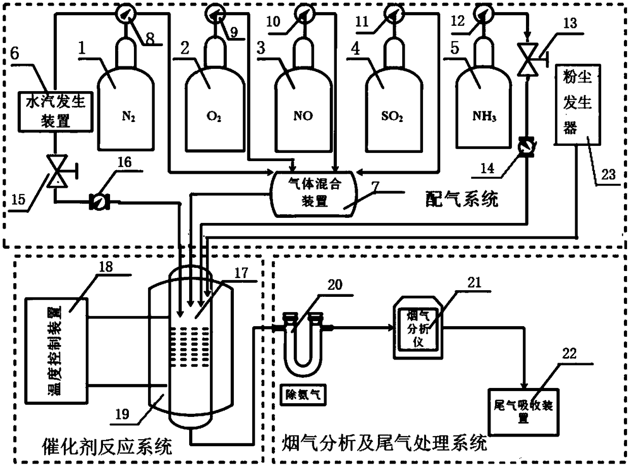
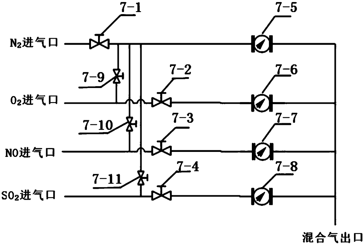
[0057] Place 2ml of the catalyst to be tested in the catalyst reactor 17, open the nitrogen gas inlet unit 1, and open the gas flow control valve 7-1, slowly feed nitrogen into the catalyst reaction system, and use the nitrogen pressure reducing valve 8 to stabilize the pressure At about 0.4MPa, keep it stable for 10 minutes, then use the method of brushing neutral foaming agent to check for leaks at all sealing points, and the next test can only be carried out after the leak test is qualified.

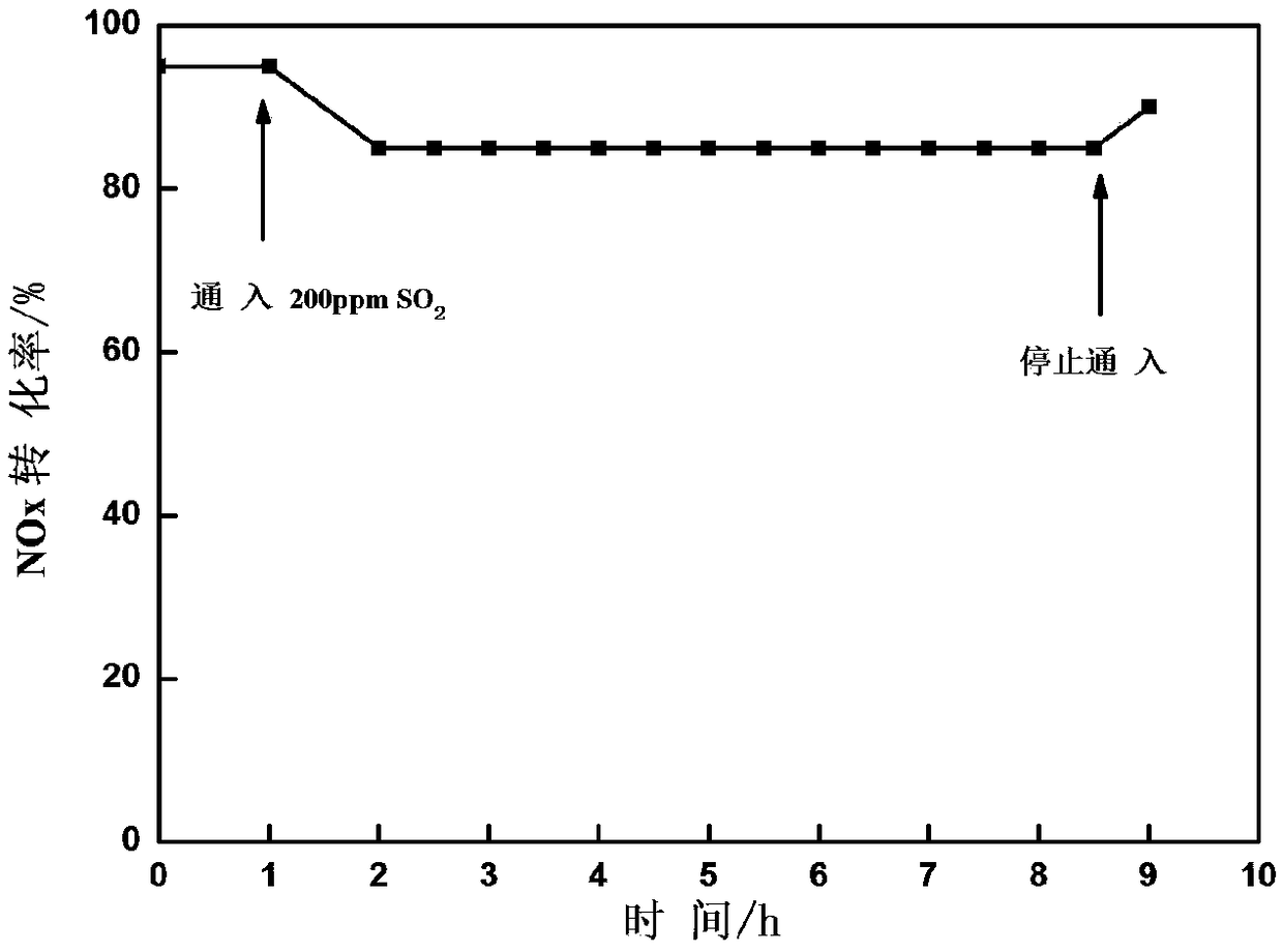
[0058] Open the oxygen intake unit 2 and the nitric oxide intake unit 3, and open the gas circulation control valves 7-2, 7-3, so that the oxygen and nitric oxide gases pass through the pressure reducing valves 9, 10 and the gas mixing device 7. Into the catalyst reactor 17, open the ammonia gas intake unit 5, pass through the pressure reducing valve 12, the gas circulation control valve 13, the mass flow meter 14 and then pass into the catalyst reactor 17, the gas composition is 800pp...

Embodiment 2

[0060] Place 2ml of the catalyst to be tested in the catalyst reactor 17, open the nitrogen gas inlet unit 1, and open the gas flow control valve 7-1, slowly feed nitrogen into the catalyst reaction system, and use the nitrogen pressure reducing valve 8 to stabilize the pressure At about 0.4MPa, keep it stable for 10 minutes, then use the method of brushing neutral foaming agent to check for leaks at all sealing points, and the next test can only be carried out after the leak test is qualified.

[0061] Open the oxygen intake unit 2 and the nitric oxide intake unit 3, and open the gas circulation control valves 7-2, 7-3, so that the oxygen and nitric oxide gases pass through the pressure reducing valves 9, 10 and the gas mixing device 7. Enter in the catalyst reactor 17, open the ammonia gas intake unit 5, pass in the catalyst reactor 17 after the pressure reducing valve 12, the gas circulation control valve 13, the mass flow meter 14, open the ammonia gas intake unit 5, After...

Embodiment 3

[0063] Place 2ml of the catalyst to be tested in the catalyst reactor 17, open the nitrogen gas inlet unit 1, and open the gas flow control valve 7-1, slowly feed nitrogen into the catalyst reaction system, and use the nitrogen pressure reducing valve 8 to stabilize the pressure At about 0.4MPa, keep it stable for 10 minutes, then use the method of brushing neutral foaming agent to check for leaks at all sealing points, and the next test can only be carried out after the leak test is qualified.

[0064] Open the oxygen intake unit 2 and the nitric oxide intake unit 3, and open the gas circulation control valves 7-2, 7-3, so that the oxygen and nitric oxide gases pass through the pressure reducing valves 9, 10 and the gas mixing device 7. Enter in the catalyst reactor 17, open the ammonia gas intake unit 5, pass in the catalyst reactor 17 after the pressure reducing valve 12, the gas circulation control valve 13, the mass flow meter 14, open the ammonia gas intake unit 5, After...


PUM


Abstract

The invention relates to a testing device and testing method of sulfur-resisting and water-resisting performance of a low-temperature flue gas denitrification catalyst for a cement kiln. The testing device comprises a gas distribution system, a catalyst reaction system and a flue gas analysis and tail gas treatment system; a nitrogen gas inlet unit, an oxygen gas inlet unit, a nitric oxide gas inlet unit and a sulfur dioxide gas inlet unit are connected with a gas mixing device respectively; the gas mixing device is connected with a catalyst reactor; the nitrogen gas inlet unit is connected with the catalyst reactor; the nitrogen gas inlet unit is also connected with a water steam generation device; the water steam generation device is connected with the catalyst reactor; the catalyst reaction system comprises the catalyst reactor, a temperature control device and a tubular heating furnace. The testing device can be used for effectively preventing errors caused by catalytic performanceof a stainless steel pipe on a test and the accuracy of a testing result is improved.

Description

technical field [0001] The invention relates to a test device and a test method for the sulfur and water poisoning resistance of a catalyst, in particular to a test device and a test method for the sulfur and water resistance of a low-temperature flue gas denitrification catalyst used in a cement kiln. Background technique [0002] Nitrogen oxides (NO x ) is one of the main pollutants in the atmosphere, with NO and NO 2 The largest proportion. Nitrogen oxides can cause great harm to the human body and the environment. The Selective Catalytic Reduction (SCR) process is currently the main technology to control the emission of nitrogen oxides from stationary sources. At present, the most widely used in industry is V with medium temperature (300°C-400°C) activity 2 o 5 -WO 3 / TiO 2 Catalyst, in order to take advantage of flue gas temperature, V 2 o 5 -WO 3 / TiO 2 Catalysts are usually arranged before the dust removal and desulfurization devices, while the low-temperatu...

Claims


Application Information

Patent Timeline
IPC IPC(8): G01N31/10
CPCG01N31/10
Inventor 薛刚桂鹏梁金生赵光远李家昂
Owner HEBEI UNIV OF TECH
Learn More