Etching reactants and plasma-free oxide etching processes using the same

A reaction, silicon oxide technology, applied in chemical instruments and methods, cleaning methods and utensils, electrical solid devices, etc., can solve problems such as slow etching rates

Active Publication Date: 2018-07-31
LAIR LIQUIDE SA POUR LETUDE & LEXPLOITATION DES PROCEDES GEORGES CLAUDE
View PDF17 Cites 3 Cited by
  • Summary
  • Abstract
  • Description
  • Claims
  • Application Information

AI Technical Summary

Problems solved by technology

However, the etch rate is too slow (approximately ) are

Method used


Image

  • Etching reactants and plasma-free oxide etching processes using the same
  • Etching reactants and plasma-free oxide etching processes using the same
  • Etching reactants and plasma-free oxide etching processes using the same

Examples


example 1

[0271] Example 1: via NbF 5 Etched oxide layer test

[0272] by atomic layer deposition and Thick Nb 2 o 5 、 Ta 2 o 5 , ZrO 2 , HfO 2 、TiO 2 and Al 2 o 3 layer deposited on a silicon substrate. The thickness of these layers was determined using ellipsometry. Those of ordinary skill in the art will recognize that scanning electron microscopy (SEM), transmission electron microscopy (TEM), X-ray photoelectron spectroscopy (XPS), secondary ionization mass spectrometry (SIMS), or Russian Electron spectroscopy (AES) was used to measure the thickness of the layer before and after etching.

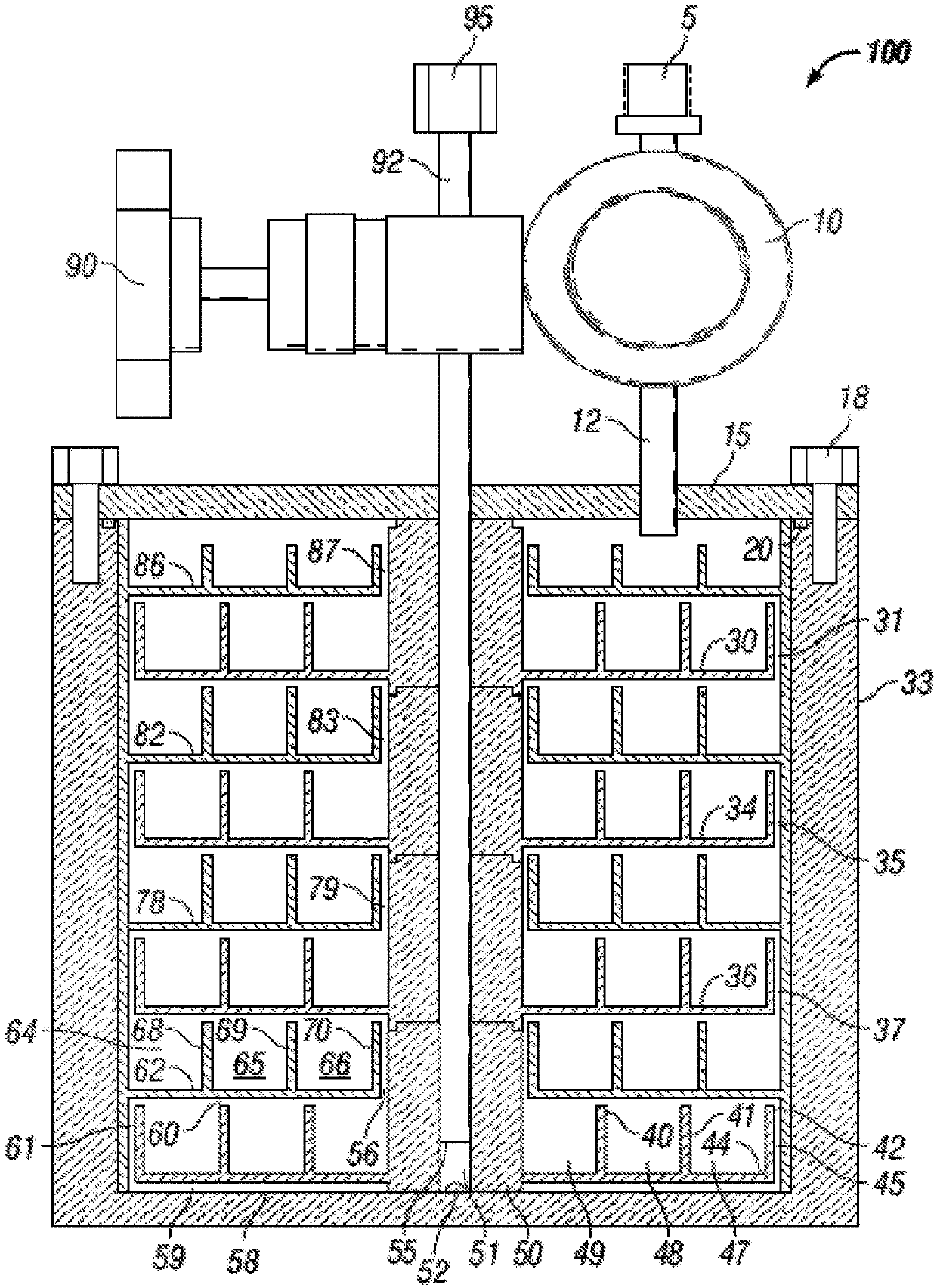
[0273] Nb via the load lock chamber 102 2 o 5 、 Ta 2 o 5 , ZrO 2 , HfO 2 、TiO 2 and Al 2 o 3 substrate and Thick SiO 2 The substrate is introduced into Figure 4 The thermal reactor 400 is placed on the wafer stage 101 heated to 200°C, 300°C, 350°C or 400°C. Reactor 400 is maintained at a pressure of 5 to 6 Torr. NbF 5 Placed in sublimator vessel 200 heated to 74°C a...

example 2

[0284] Example 2: Via NbF 5 Etched nitride layer test

[0285] Preparation of TiN TaN and SiN Floor. The substrate containing the nitride layer is introduced via the load lock chamber 102 into Figure 4 The thermal reactor 400 is placed on the wafer stage 101 heated to 350°C, 400°C or 425°C. The reactor 400 pressure was fixed at 5 to 6 Torr. NbF 5 Place in vessel 200 heated to 74°C and introduce its vapor into reactor 400 with Ar carrier gas 300 at 255 seem. The thicknesses of the TiN and TaN layers were measured using a scanning electron microscope (SEM) after 5 seconds, 10 seconds, 15 seconds, and 30 seconds. The thickness of the SiN layer was measured after 30 seconds and 90 seconds using an ellipsometer. The film thickness of any of the nitride films was unchanged and etching was not observed at any temperature. Table 2 shows that with NbF 5 Film etch rate as a function of time and temperature summary.

[0286] Table 2 by NbF 5 Summary of Nitride Etch Rat...

example 3

[0290] Example 3: via VF 5 Tests for etching oxide and nitride layers

[0291] Nb via the load lock chamber 102 2 o 5 、 Ta 2 o 5 , ZrO 2 , HfO 2 、TiO 2 、Al 2 o 3 , SiO 2 , TiN and TaN substrates introduced into Figure 4 The thermal reactor 400 is placed on the wafer stage 101 heated to 150°C, 200°C, 300°C, 350°C or 400°C.

[0292] Reactor 400 is maintained at a pressure of 5 to 6 Torr. will VF 5 Place in container 200 at room temperature. Vapor is continuously introduced into reactor 400 without any carrier gas.

[0293] Image 6 Display with VF 5 The thickness of the different oxide layers is introduced as a function of time and temperature. Introduction of total VF at 150°C 5 After 30 seconds and 90 seconds; at 200°C after 10 seconds and 30 seconds; at 300°C after 3 seconds, 5 seconds, 6 seconds, 8 seconds and 30 seconds; at 350°C for 2 seconds, 3 seconds, 5 seconds , after 10 seconds and 30 seconds; and after 1 second, 2 seconds, 3 seconds, 5 seconds, 1...


PUM

PropertyMeasurementUnit
Thicknessaaaaaaaaaa

Abstract

Disclosed are processes of removing layers from substrates using fluorinated reactants having the formula MFx(adduct)n, wherein x ranges from 2 to 6 inclusive; n ranges from 0 to 5 inclusive; M is selected from the group consisting of P, Ti, Zr, Hf, V, Nb, Ta, Mo, and W; and the adduct is a neutral organic molecule selected from THF, dimethylether, diethylether, glyme, diglyme, triglyme, polyglyme, dimethylsulphide, diethylsulphide, or methylcyanide. The fluorinated reactants dry etch the nitride layers without utilizing any plasma.

Description

[0001] Cross References to Related Applications [0002] This application claims the benefit of US Provisional Application Serial No. 62 / 253,507, filed November 10, 2015, which is hereby incorporated by reference in its entirety for all purposes. technical field [0003] Disclosed is the use of MF with formula x (adduct) n A thermal method for removing a layer from a substrate by a fluorinated reactant of wherein x is in the range from 2 to 6, inclusive; n is in the range from 0 to 5, inclusive; M is selected from the group consisting of The elements of the group: P, Ti, Zr, Hf, V, Nb, Ta, Mo and W; and the adduct is a neutral organic molecule selected from THF, dimethyl ether, diethyl ether, ethylene glycol dimethyl ether , Diethylene glycol dimethyl ether, triethylene glycol dimethyl ether, polyethylene glycol dimethyl ether, dimethyl sulfide, diethyl sulfide or methyl cyanide. These fluorinated reactants dry etch these layers without using any plasma. Background techni...

Claims


Application Information

Patent Timeline
IPC IPC(8): H01L21/3065H01L21/8238H01L21/02
CPCH01L21/31122H01L21/02244H01L21/31116H01L21/32135H01L21/67069C23F1/12H01L21/0212H01L21/3065H01L21/8238H01L2924/01009H01L2924/35121B08B9/083C23C8/80H01L21/02247
Inventor 克莱蒙特·兰斯洛特-马特拉斯李柱昊让-马克·吉拉尔尼古拉斯·布拉斯科伽蒂诺谕子
Owner LAIR LIQUIDE SA POUR LETUDE & LEXPLOITATION DES PROCEDES GEORGES CLAUDE
Why Eureka
Try Eureka